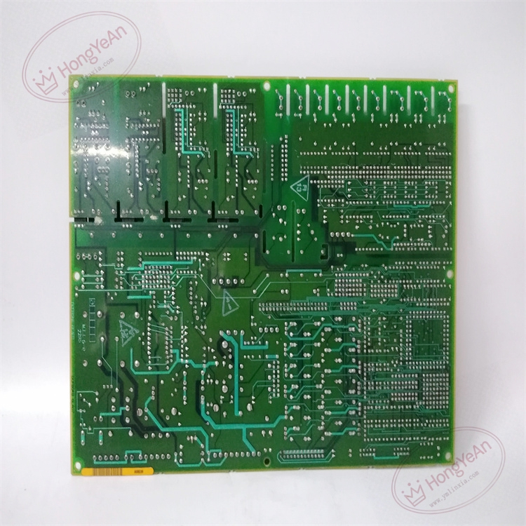
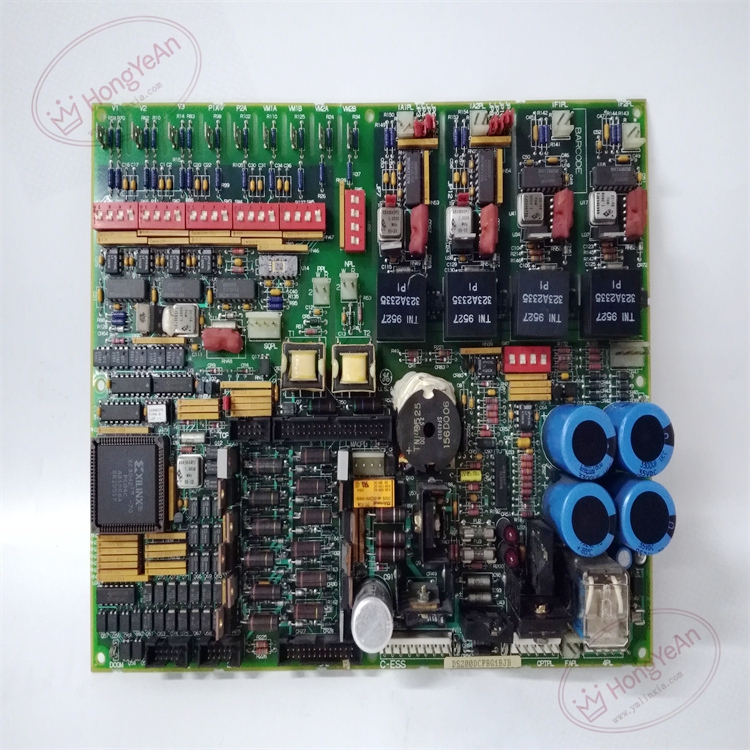
Description
Hardware & Electrical Specifications
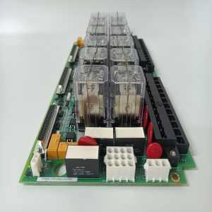
‑ Model: DS200DCFBG1BJB ‑ Part Number: DS200DCFBG1BJB ‑ Module Type: Mark V / EX2000 DC Feedback Power PCB Board ‑ Mounting: Standoff screw‑fastened installation inside Mark V drive‑control cabinet ‑ Input power: 38 VAC and 115 VAC sourced from system CPT transformer ‑ Output power rails: +5 VDC, ±15 VDC, ±24 VDC control‑level power; 115 VAC fan supplyassets.eua… ‑ Configuration components: 12 on‑board jumpers, 7 DIP‑switches for drive‑mode and feedback‑scaling setupassets.eua… ‑ Protection: Three replaceable fuses, over‑voltage, over‑current and short‑circuit protection for power branches ‑ Connectors: 18 plug‑in connectors, 9 stab‑type system‑bus connectors for drive‑system interconnection ‑ Diagnostics resources: 2 LED indicators, 1 neon fuse‑status indicator, 5 hardware test‑points for signal measurement ‑ Isolation: Galvanic isolation between high‑power drive‑stage circuits and low‑voltage logic sections ‑ PCB treatment: Industrial conformal‑coated multilayer circuit board (‑JB hardware revision) ‑ Compatibility note: Designed for GE Speedtronic Mark V, EX2000 excitation system and AC2000 / DC2000 / CB2000 drives; not drop‑in compatible with Mark VI / Mark VIe platforms. After replacement, strictly copy original DIP‑switch and jumper settings, verify all connector seating, measure each DC output rail, confirm feedback‑signal accuracy and drive‑system responseassets.eua….
Environmental Specifications
‑ Operating temperature: 0 ℃ ~ +60 ℃ ‑ Storage temperature: −40 ℃ ~ +85 ℃ ‑ Relative humidity: 5%‑95% non‑condensing ‑ Installation location: Indoor control cabinet, Pollution Degree 2, IP20 ‑ EMC compliance: Industrial EMC requirements for power‑turbine and excitation‑control equipment ‑ Certifications: CE, UL compliant for power‑generation control‑system components
Mechanical Data
‑ Board dimension: approx 240 mm × 175 mm ‑ Mounting: Multi‑standoff fixed mounting inside drive cabinet ‑ Weight: approx 0.65 kg
Main Functions
- Converts transformer‑supplied AC input into multi‑channel regulated DC control power for drive‑logic boards, and provides 115 VAC power for cabinet cooling fans.
- Implements DC‑field voltage feedback monitoring, converts feedback signals for SDCC/LDCC drive‑control boards; DIP‑switch settings adjust feedback‑signal scaling for different drive‑hardware configurations.
- Hardware fuses and protective circuits isolate power‑branch faults to limit component damage. On‑board indicators and test‑points support on‑site fault‑isolation and maintenance measurement.
Installation & Wiring Requirements
- Cut off complete rack and drive‑unit power supply before installation or replacement. Non‑hot‑swappable. ESD wrist‑strap protection is mandatory during board handling.
- Secure DS200DCFBG1BJB to cabinet stand‑offs. Reproduce DIP‑switch and jumper‑configuration exactly matching the original board hardware settings. Seat all plug‑in and stab‑type connectors firmlyassets.eua….
- All power‑circuit wiring must strictly follow Mark V / EX2000 system wiring drawings. Reliable protective‑earth connection for control cabinet is mandatory.
- After replacement: Restore system power supply. Measure every regulated DC output rail against nominal values. Verify fuse‑status indicators. Check excitation‑drive feedback‑signal readings and validate drive‑regulation performance.
- Replacement note: Incorrect DIP‑switch or jumper configuration will cause excitation‑drive mis‑regulation, equipment damage or turbine‑trip events. Full‑system commissioning and protection‑logic verification test is mandatory before putting turbine‑generator excitation‑control into service.
Reviews
There are no reviews yet.