Description
Physical features
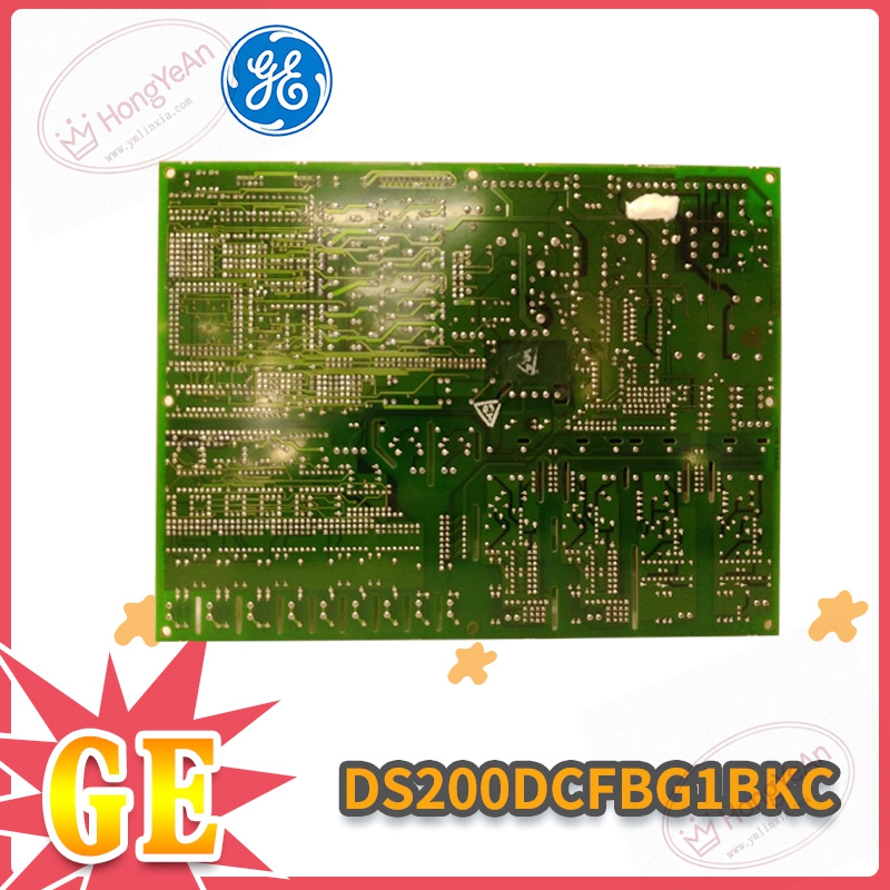
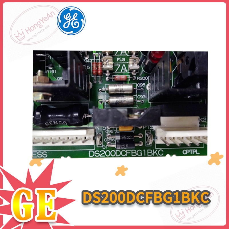
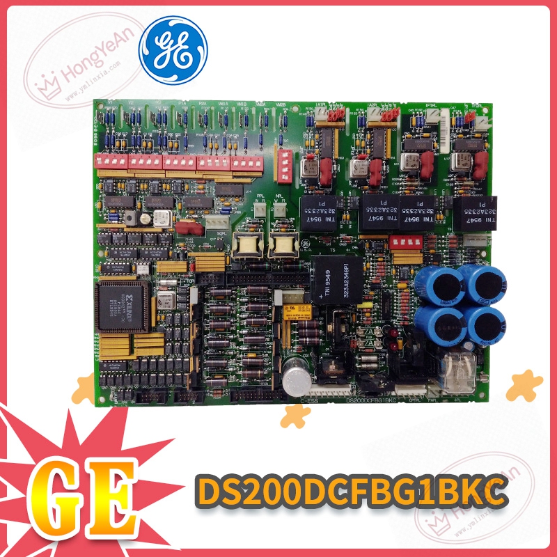
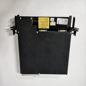
Standard printed‑circuit plug‑in board for Mark‑V chassis. ‑ Board surface: multiple electrolytic capacitors, relay components, DIP toggle switches and jumper banks for function configuration. ‑ Front edge: multiple plug‑in connectors for power input, signal and fan load output. Two LED plus one neon lamp for fuse and fault status indication. ‑ Rear edge: gold‑finger contacts for connecting rack back‑plane bus. ‑ Silkscreen label printed with part‑number DS200DCFBG1BKC on PCB surface. ‑ No independent metal housing, directly inserted into the rack slot.
Main parameters
Input: 38‑115 VAC control power supply. Built‑in 3‑way fuses for short‑circuit protection. Equipped with 7 DIP switches and 12 jumpers for on‑site function setting. Reserved 5 test points for voltage measurement and troubleshooting. Operating temperature range‑40℃ ~ +70℃, cabinet‑internal installation only, IP20. Compatible systems: Mark‑V Speedtronic, AC2000, DC2000 series drive control racks.
Practical usage
Installed inside power‑plant turbine control cabinets. This board supplies stable working power for CPU and various I/O cards, meanwhile supplies power for cabinet cooling fans. If this board fails, partial or whole rack will lose power, which may cause turbine trip. After replacement, set jumpers and DIP switches consistent with original configuration, check multi‑group output voltage, verify fan driving function before online running.
Installation reminders
Recommend power‑off operation for card replacement, reduce scratch risk to gold‑finger contacts. Keep cabinet well‑ventilated. High temperature will accelerate aging of electrolytic capacitors on board and cause voltage drift. Signal and power cables should keep distance from high‑power cables to avoid surge interference. Do not repair components on‑site; replace whole PCB board once hardware damage occurs.
Common troubleshooting
- Indicator lamps all off after power‑on: Check AC input voltage and connector locking status. Inspect internal fuses for blow‑out.
- Output voltage unstable / offset: Observe cabinet ambient temperature, check aging of electrolytic capacitors.
- Fan cannot run: Check fan power output circuit, DIP‑switch setting and load loop.
- Intermittent system fault alarm: Clean dust on PCB surface, check connector fastening, eliminate vibration influence.
-300x300.jpg)
-1-1-300x300.jpg)
Reviews
There are no reviews yet.