Description
Physical appearance
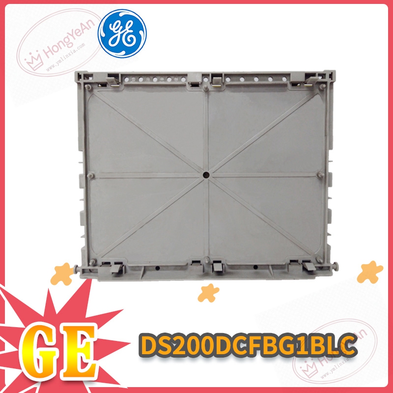
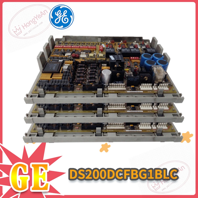
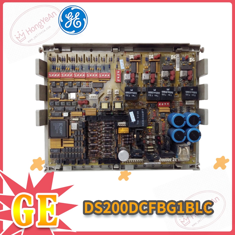
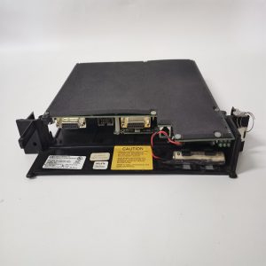
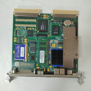
Standard plug‑in printed circuit board, insert horizontally into Mark‑V rack slot. ‑ PCB surface: large‑volume electrolytic capacitors, relay components, DIP toggle switches and jumper groups for function configuration. ‑ Front edge: multiple plug‑in connectors for power input, signal and fan load output; several indicator lamps for fuse and fault state. ‑ Rear side: gold‑finger contacts for rack backplane power and internal bus communication. ‑ PCB silkscreen marks complete part‑number DS200DCFBG1BLC. No independent metal housing.
Core practical capabilities
Accept 38‑115 VAC control power input. Output stable +5V, ±15V, ±24V multi‑group DC control power. Equipped with 12 jumpers,7 DIP switches for field function adjustment; 3 built‑in fuses for short‑circuit protection; reserved 5 test points for on‑site voltage measurement. Integrated VCO voltage‑controlled oscillator circuit, converts motor field voltage feedback into frequency signal for main controller processing. It also outputs driving signal for cabinet cooling fans. Operating ambient:‑40℃ ~ +70℃, IP20, only install inside control cabinet. Note: Jumper and DIP‑switch setting must keep consistent with original parameters after replacement, otherwise power output and feedback function will be abnormal.
Real‑world usage
Installed inside power‑plant turbine control cabinet. This board supplies stable working power for each internal card, collects power feedback signal and drives cabinet cooling fans. If this board fails, partial or whole rack loses power, may trigger unit protective trip. After replacement, strictly copy original jumper & DIP‑switch setting, measure each group DC output voltage, verify fan running status and feedback signal before putting into online operation.
Installation reminders
Power‑off operation is recommended for replacing this PCB card, avoid scratch and oxidation damage to back‑plane gold‑finger contacts. Reserve heat‑dissipation space around rack. High cabinet temperature will accelerate aging of board‑mount electrolytic capacitors and cause output drift. Power and signal wiring shall keep distance from high‑power cables to restrain surge interference. Do not disassemble PCB for component‑level repair. Replace whole circuit board once hardware damage occurs.
Typical troubleshooting
- All indicator lamps stay dark after power‑on: Check AC control power input and connector locking; inspect internal fuse blow‑out risk.
- DC output value offset / unstable: Confirm jumpers and DIP‑switch consistent with original setting; check cabinet ambient temperature and capacitor aging condition.
- Fan cannot run normally: Inspect fan wiring connector, check fan driving circuit parameter on board.
- Intermittent system fault alarm: Clean PCB surface dust, check rack anti‑vibration condition, eliminate surrounding electromagnetic interference.
Reviews
There are no reviews yet.