Description
Hardware & Electrical Specifications
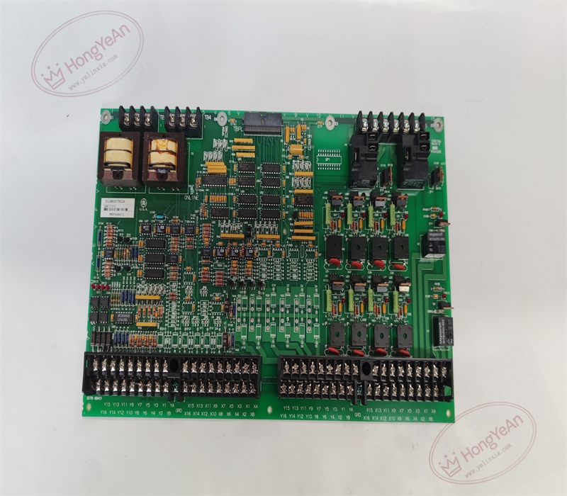
‑ Model: DS200DDTBG1A ‑ Part Number: DS200DDTBG1A ‑ Module Type: Mark V / LS2100 LCI Auxiliary I/O Terminal PCB Board ‑ Mounting: Screw‑fastened installation inside Mark V control cabinet rack ‑ Connectors: • Multi‑position field‑wiring terminal blocks for field‑sensor and actuator wiring • System bus headers for connection to IS200ADMAH1A ADMA board ‑ Configuration components: 12 on‑board hardware jumpers, 3 sets of DIP‑switches for channel‑mode and input‑type assignment ‑ Signal support: 4‑20 mA analog loop inputs, high‑voltage AC inputs, LEM/CT current‑feedback inputs, 4 buffered analog outputs ‑ Power supply: Logic power supplied from Mark V system backplane ‑ Isolation: Galvanic isolation between field‑side signals and internal controller logic circuits ‑ Diagnostics resources: 17 on‑board LED status indicators (DS1‑DS17) for hardware and software driven channel status display ‑ PCB treatment: Standard industrial conformal‑coated multilayer circuit board ‑ Compatibility note: Designed exclusively for GE Speedtronic Mark V and LS2100 static‑starter platforms; not drop‑in compatible with Mark VI / Mark VIe systems. After replacement, verify jumper and DIP‑switch settings match original unit, tighten all field‑wiring and system‑bus connectors, perform signal‑loop injection tests and validate controller I/O readings.
Environmental Specifications
‑ Operating temperature: 0 ℃ ~ +60 ℃ ‑ Storage temperature: −40 ℃ ~ +85 ℃ ‑ Relative humidity: 5%‑95% non‑condensing ‑ Installation location: Indoor control cabinet, Pollution Degree 2, IP20 ‑ EMC compliance: Industrial control EMC requirements for power‑turbine and static‑starter equipment ‑ Certifications: CE, UL compliant for power‑generation control‑system components
Mechanical Data
‑ Board dimension: 203.2 mm (8 in) width × 152.4 mm (6 in) length ‑ Mounting: Four‑point screw fixed mounting onto cabinet card rack ‑ Weight: approx 0.50 kg
Main Functions
- Provides signal conditioning, termination and galvanic isolation for LCI static‑starter and turbine‑auxiliary I/O signals between field‑mounted sensors, CT/LEM transducers and the Mark V ADMA/DSPC control hardware. Converts raw field‑measurement signals into compatible levels for DSP processing.
- On‑board jumpers and DIP‑switches enable channel‑configuration for different signal types without modifying other system boards. 17 LED indicators offer direct visual channel‑status observation for on‑site maintenance troubleshooting.
- Four buffered analog output channels deliver conditioned control signals to external drive‑related equipment. Integrated surge‑suppression components protect control‑system electronics from field‑side transient noise.
Installation & Wiring Requirements
- Cut off complete rack power supply before installation or replacement. Non‑hot‑swappable. ESD wrist‑strap protection is mandatory during board handling.
- Secure DS200DDTBG1A onto cabinet rack with four mounting screws. Reproduce jumper‑setting and DIP‑switch‑configuration exactly matching the original hardware settings. Secure field‑wiring terminals and system‑bus headers firmly.
- All field wiring must strictly follow Mark V / LS2100 system wiring drawings. Reliable protective‑earth connection for control cabinet is mandatory.
- After replacement: Restore rack power supply. Verify LED status indications. Inject test signals for each analog input channel and confirm controller read‑back accuracy. Validate static‑starter related control‑loop response.
- Replacement note: Misconfigured jumpers or DIP‑switches will result in incorrect signal scaling, static‑starter malfunction or turbine‑trip events. Full‑system commissioning and protection‑logic verification test is mandatory before putting turbine‑starter control into service.
-300x300.jpg)
Reviews
There are no reviews yet.