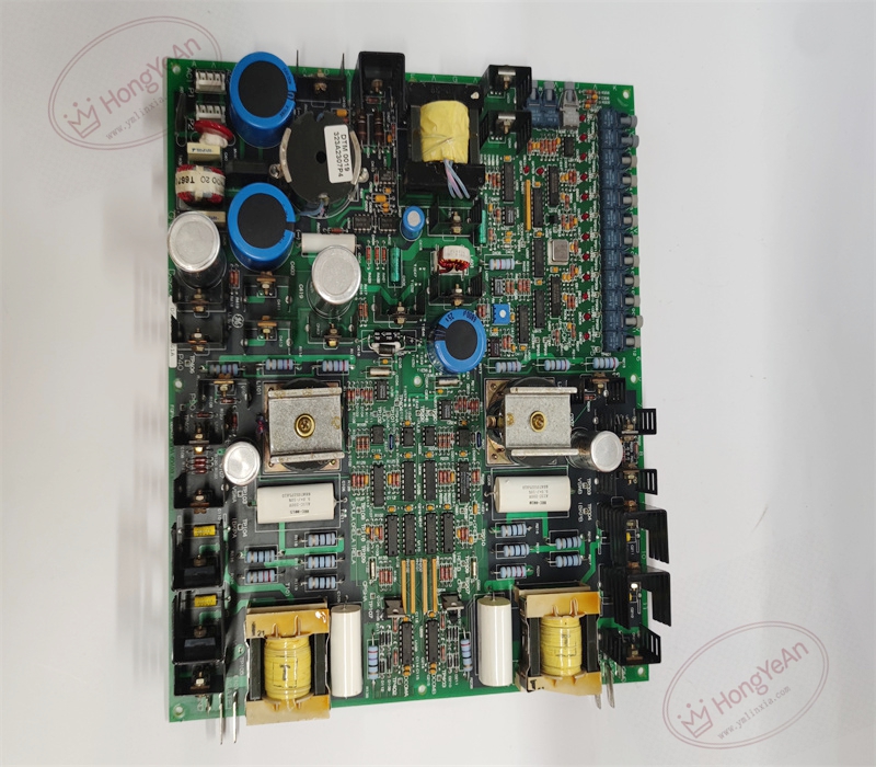

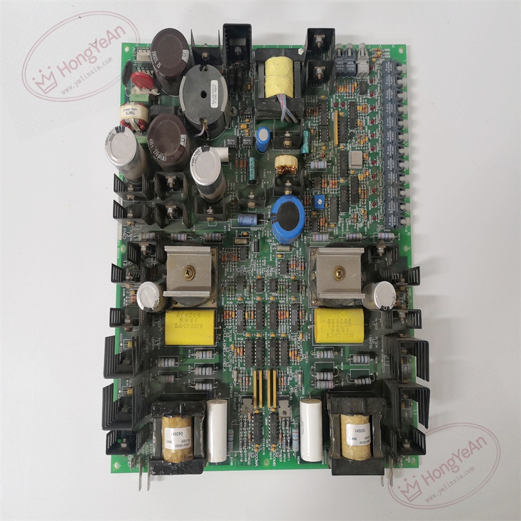
Description
Hardware & Electrical Specifications
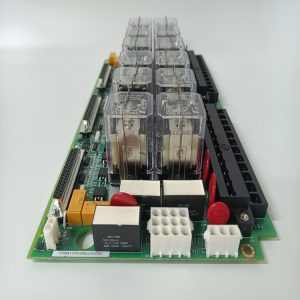
‑ Model: DS200FGPAG1A ‑ Part Number: DS200FGPAG1A ‑ Module Type: Mark V / LS2100 LCI Gate Pulse Amplifier PCB Board (FGPA) ‑ Mounting: Rack‑mount installation inside LS2100 high‑voltage drive cabinet ‑ AC Input Power: Rated 115‑230 VAC; allowable range 90‑260 VAC; 50‑60 Hz (47‑63 Hz tolerance); max 350 VA ‑ Gate Driver Circuits: 2 independent gate‑drive circuits for one‑phase SCR bridge control ‑ Fiber‑Optic Interfaces: 15 fiber‑optic ports; 1 transmit port, 14 receive ports; provides high‑voltage galvanic isolation for control signals ‑ Test & Monitoring Points: 30 on‑board test points for gate‑drive output and SCR cell‑status measurement ‑ Protection: 2.5 AT glass fuse; over‑voltage, under‑frequency and supply‑fault protection circuits ‑ Connectors: Multiple fiber‑optic ports; AC power input terminals; SCR‑status signal interfaces ‑ Diagnostics resources: Multiple LED status indicators for power supply, fiber‑link activity and hardware‑fault alarms ‑ PCB treatment: Industrial conformal‑coated multilayer circuit board ‑ Compatibility note: Designed exclusively for GE Speedtronic Mark V and LS2100 LCI static‑starter platforms; not drop‑in compatible with Mark VI / Mark VIe systems. After replacement, verify fiber‑optic cable routing and bend radius, check all LED status, perform gate‑pulse static test and SCR‑status signal validation before applying high‑voltage power.
Environmental Specifications
‑ Operating temperature: 0 ℃ ~ +60 ℃ ‑ Storage temperature: −40 ℃ ~ +85 ℃ ‑ Relative humidity: 5%‑95% non‑condensing ‑ Installation location: Indoor high‑voltage drive cabinet, Pollution Degree 2, IP20 ‑ EMC compliance: Industrial EMC requirements for power‑turbine and static‑starter high‑power‑electronics equipment ‑ Certifications: CE, UL compliant for power‑generation control‑system components
Mechanical Data
‑ Board dimension: approx 225 mm × 144 mm × 96 mm ‑ Mounting: Cabinet rack‑mount assembly ‑ Weight: approx 2.5 kg
Main Functions
- Built‑in switching power supply converts field‑side AC input into multiple isolated DC power rails for gate‑drive circuits and SCR‑status‑monitoring circuits.
- Receives optical firing‑pulse commands from FCGD board, amplifies optical signals into high‑energy gate‑drive pulses to trigger SCR thyristors for one phase of the LCI power bridge.
- Collects SCR cell‑voltage health‑status data from FHVA assemblies, packages status data and sends back to LCI controller over fiber‑optic serial link for fault‑diagnosis and trip‑logic processing.
- Thirty on‑board test‑points and LED indicators support on‑site commissioning, pulse‑output inspection and field‑fault‑isolation maintenance.
Installation & Wiring Requirements
- Cut off complete rack low‑voltage power and high‑voltage static‑starter power before installation or replacement. Non‑hot‑swappable. ESD wrist‑strap protection is mandatory during board handling.
- Secure DS200FGPAG1A onto cabinet rack. Route fiber‑optic cables following specified minimum bend radius; firmly seat all fiber‑optic connectors and AC‑power‑input terminals. Do not over‑tighten fiber‑optic connectors.
- All AC‑power wiring and fiber‑optic cabling must strictly follow Mark V / LS2100 system‑wiring drawings. Reliable protective‑earth connection for control cabinet is mandatory.
- After replacement: Restore AC auxiliary power first. Observe LED power‑supply and fiber‑link status. Measure gate‑pulse output via on‑board test‑points during static test. Verify SCR‑cell‑status feedback values from controller diagnostic menus. Complete static firing‑test before applying high‑voltage main‑power; validate static‑starter commutation performance.
- Replacement note: Improper fiber‑optic routing, loose connectors or power‑supply mis‑wiring will cause gate‑pulse loss, SCR mis‑fire, bridge‑commutation failure or turbine‑trip events. Full‑system commissioning and protection‑logic verification test is mandatory before putting static‑starter into service.
-1-300x300.jpg)
Reviews
There are no reviews yet.