Description
Hardware & Electrical Specifications
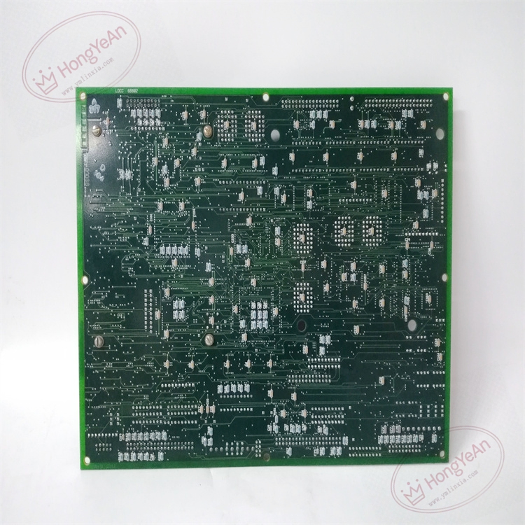
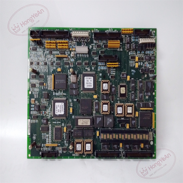
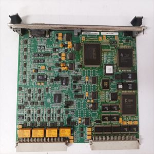
‑ Model: DS200LDCCH1ANA ‑ Part Number: DS200LDCCH1ANA ‑ Module Type: Mark V / EX2000 Drive‑Control & LAN‑Communication VME PCB Board (LDCC) ‑ Mounting: Standard 6U VME slide‑in rack‑mount installation with front‑panel ejector latches ‑ Power supply: +5 VDC, ±15 VDC supplied from VME system backplane; typical power consumption approx 8‑12 W ‑ On‑board Processors: LCP, DCP, MCP, CMP four‑processor parallel‑processing architecture ‑ Memory: Flash PROM for firmware; EEPROM for non‑volatile user‑configuration parameters ‑ Communication Interfaces: VME backplane interface; supports DLAN+, DLAN, Genius, CPL, C‑BUS multi‑bus protocols; RS‑232 local debug port; RS‑485 diagnostic interface ‑ Configuration components: 14 on‑board hardware jumpers for rack‑address, operating‑mode and communication‑bus selection; partial jumpers reserved for factory test only ‑ Operator Interface: Integrated membrane alphanumeric keypad; hardware manual reset push‑button ‑ Diagnostics resources: Front‑panel multi‑LED array for power‑status, processor‑health, bus‑link and drive‑fault‑alarm indication ‑ Isolation: Galvanic isolation between field‑I/O acquisition circuits and internal logic sections ‑ PCB treatment: Industrial conformal‑coated multilayer circuit board (‑ANA hardware revision, improved power‑filter circuit) ‑ Compatibility note: Designed exclusively for GE Speedtronic Mark V, EX2000 excitation system and DIRECTO‑MATIC 2000 DC‑drive platforms; not drop‑in compatible with Mark VI / Mark VIe systems. After replacement, strictly reproduce original jumper‑configuration, guarantee dual VME backplane connectors fully engaged, verify keypad & reset‑button function, check bus‑communication status, download matching firmware version and validate drive closed‑loop performance.
Environmental Specifications
‑ Operating temperature: 0 ℃ ~ +60 ℃ ‑ Storage temperature: −40 ℃ ~ +85 ℃ ‑ Relative humidity: 5%‑95% non‑condensing ‑ Installation location: Indoor turbine / drive control cabinet, Pollution Degree 2, IP20 ‑ EMC compliance: Industrial EMC requirements for power‑generation excitation‑drive and turbine‑control‑room equipment ‑ Certifications: CE, UL compliant for power‑plant control‑system components
Mechanical Data
‑ Board dimension: 233 mm × 160 mm (standard 6U VME form‑factor) ‑ Mounting: VME rack slide‑in assembly with front‑panel ejector latches ‑ Weight: approx 0.92 kg
Main Functions
- Four‑processor parallel‑computing architecture completes real‑time drive‑control algorithm for EX2000 generator‑excitation and DIRECTO‑MATIC 2000 DC‑drives: processes analog‑digital I/O signals, encoder position‑feedback, executes firing‑angle calculation and drive‑reference‑command output to downstream power‑control boards.
- Multi‑bus communication gateway function: exchanges set‑point values, operating‑status and fault‑alarm data with Mark V main CPU and peripheral I/O devices over multiple industrial bus channels. Local RS‑232 / RS‑485 ports support off‑line parameter‑configuration and diagnostic debugging.
- Integrated keypad and reset button realize on‑site drive‑parameter modification, fault‑code browsing, manual drive‑reset operations. 14 hardware jumpers configure rack‑address, operating‑mode and communication‑bus selection.
- Front‑panel LED indicators support commissioning, real‑time status‑monitoring and field‑fault‑isolation maintenance. Non‑volatile EEPROM preserves user‑configuration parameters during power‑cycle events.
Installation & Wiring Requirements
- Cut off rack low‑voltage control power and high‑voltage excitation‑drive power before installation or replacement. Non‑hot‑swappable. ESD wrist‑strap protection is mandatory during board handling.
- Insert DS200LDCCH1ANA into target VME slot, push fully home to engage dual rear VME backplane connectors and actuate front‑panel ejector latches to lock. Reproduce jumper‑settings strictly consistent with original‑board hardware configuration; do not alter factory‑reserved test jumpers. Confirm all external communication‑port connectors are fully seated.
- All communication‑cable and field‑signal wiring must strictly follow Mark V / EX2000 system‑wiring drawings. Reliable protective‑earth connection for control cabinet is mandatory.
- After replacement: Restore rack low‑voltage power first. Observe front‑panel LED power, processor‑health and bus‑link status. Test keypad input and hardware reset‑button response. Confirm communication‑data exchange with Mark V CPU. Complete static‑signal‑verification test before applying high‑voltage drive‑power; validate excitation‑drive closed‑loop‑regulation performance.
- Replacement note: Incorrect jumper‑configuration, poor VME‑backplane contact or firmware‑version mismatch will cause communication‑interruption, drive‑algorithm‑abnormality, excitation‑mis‑operation or unit‑trip‑events. Full‑system communication‑function, drive‑control‑loop and protection‑logic‑verification test is mandatory before putting turbine‑generator excitation‑drive into service.
Reviews
There are no reviews yet.