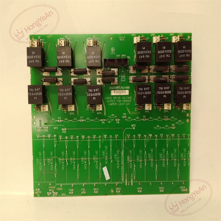
Description
Hardware & Electrical Specifications
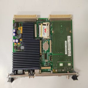
‑ Model: DS200PCCAG1ABB ‑ Part Number: DS200PCCAG1ABB ‑ Module Type: Mark V EX2000 / DM2000 Drive Power‑Connect Interface PCB (PCCA) ‑ Mounting: Screw‑fixed rack‑mount inside high‑power drive cabinet ‑ Armature Operating Range: 240‑630 V regenerative DC drive application ‑ Signal Interface: Isolated SCR gate‑pulse routing; armature voltage‑current feedback signal conditioning ‑ Configuration components: 4 on‑board configurable jumpers JP1, JP2, JP3, JP4 for capacitor‑bank and feedback‑channel setup; factory‑default jumper positions must be duplicated at replacement ‑ Connectors: Multi‑pin ribbon‑cable connectors for control‑rack side; high‑power terminal blocks for SCR‑bridge field‑wiring ‑ Power supply: Low‑voltage logic power supplied from LDCC controller board ‑ Protection: No on‑board fuses; overcurrent protection implemented by external cabinet fuses ‑ Diagnostics resources: On‑board test‑points for feedback‑signal measurement; no status LED array ‑ PCB treatment: Industrial conformal‑coated multilayer circuit board (‑ABB revision) ‑ Compatibility note: Exclusively for GE Speedtronic Mark V EX2000 excitation and DIRECTO‑MATIC 2000 DC‑drive platforms; not drop‑in compatible with Mark VI / Mark VIe systems. After replacement, strictly copy original jumper‑settings, verify all ribbon‑cable and power‑terminal tightness, check feedback‑signal amplitudes at test‑points before applying high‑voltage armature power.
Environmental Specifications
‑ Operating temperature: 0 ℃ ~ +60 ℃ ‑ Storage temperature: −40 ℃ ~ +85 ℃ ‑ Relative humidity: 5%‑95% non‑condensing ‑ Installation location: Indoor high‑power drive cabinet, Pollution Degree 2, IP20 ‑ EMC compliance: Industrial EMC requirements for power‑generation excitation‑drive equipment ‑ Certifications: CE, UL compliant for power‑plant control‑system components
Mechanical Data
‑ Board dimension: approx 275 mm × 178 mm ‑ Mounting: Four‑point screw fixed cabinet rack‑mount ‑ Weight: approx 0.45 kg
Main Functions
- Isolated signal‑path routing: transfers SCR firing‑gate pulses from LDCC controller board out to SCR power‑bridge assemblies.
- Conditions armature voltage‑current feedback signals from power‑bridge, returns scaled analog feedback to LDCC board for closed‑loop excitation‑current / DC‑motor‑speed regulation.
- Four configurable jumpers select buffer‑capacitor operating mode and voltage‑feedback‑channel configuration to match actual power‑bridge hardware setup.
- On‑board test‑measurement points support commissioning, signal‑waveform inspection and field‑fault‑isolation troubleshooting.
Installation & Wiring Requirements
- Cut off rack low‑voltage control power AND high‑voltage armature power before installation or replacement. Non‑hot‑swappable. ESD wrist‑strap protection is mandatory during board handling.
- Secure DS200PCCAG1ABB to drive‑cabinet rack. Reproduce jumper‑configuration exactly matching original‑board settings. Tighten all ribbon‑cable connectors and high‑power field‑terminal blocks.
- All field‑power and signal‑cable wiring must strictly follow Mark V / EX2000 system‑wiring drawings. Reliable protective‑earth connection for drive cabinet is mandatory.
- After replacement: Restore low‑voltage control‑power only. Measure feedback‑signal levels via on‑board test‑points. Complete static‑signal‑validation test before applying high‑voltage armature power; verify excitation‑drive closed‑loop regulation performance.
- Replacement note: Wrong‑jumper‑configuration, loose terminals or bad ribbon‑cable contacts will cause feedback‑signal distortion, SCR mis‑fire, excitation‑regulation failure or unit‑trip‑events. Full‑system drive‑loop and protection‑logic verification test is mandatory before putting excitation‑drive into service.
Reviews
There are no reviews yet.