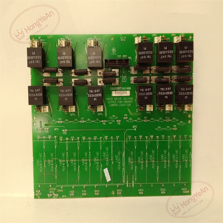
Description
Hardware & Electrical Specifications
‑ Model: DS200PCCAG1ABB ‑ Part Number: DS200PCCAG1ABB ‑ Module Type: Mark V EX2000 / DM2000 Drive Power‑Connect Interface PCB (PCCA) ‑ Mounting: Screw‑fixed rack‑mount inside high‑power drive cabinet ‑ Armature Operating Range: 240‑630 V regenerative DC drive application ‑ Signal Interface: Isolated SCR gate‑pulse routing; armature voltage‑current feedback signal conditioning ‑ Configuration components: 4 on‑board configurable jumpers JP1, JP2, JP3, JP4 for capacitor‑bank and feedback‑channel setup; factory‑default jumper positions must be duplicated at replacement ‑ Connectors: Multi‑pin ribbon‑cable connectors for control‑rack side; high‑power terminal blocks for SCR‑bridge field‑wiring ‑ Power supply: Low‑voltage logic power supplied from LDCC controller board ‑ Protection: No on‑board fuses; overcurrent protection implemented by external cabinet fuses ‑ Diagnostics resources: On‑board test‑points for feedback‑signal measurement; no status LED array ‑ PCB treatment: Industrial conformal‑coated multilayer circuit board (‑ABB revision) ‑ Compatibility note: Exclusively for GE Speedtronic Mark V EX2000 excitation and DIRECTO‑MATIC 2000 DC‑drive platforms; not drop‑in compatible with Mark VI / Mark VIe systems. After replacement, strictly copy original jumper‑settings, verify all ribbon‑cable and power‑terminal tightness, check feedback‑signal amplitudes at test‑points before applying high‑voltage armature power.
Environmental Specifications
‑ Operating temperature: 0 ℃ ~ +60 ℃ ‑ Storage temperature: −40 ℃ ~ +85 ℃ ‑ Relative humidity: 5%‑95% non‑condensing ‑ Installation location: Indoor high‑power drive cabinet, Pollution Degree 2, IP20 ‑ EMC compliance: Industrial EMC requirements for power‑generation excitation‑drive equipment ‑ Certifications: CE, UL compliant for power‑plant control‑system components
Mechanical Data
‑ Board dimension: approx 275 mm × 178 mm ‑ Mounting: Four‑point screw fixed cabinet rack‑mount ‑ Weight: approx 0.45 kg
Main Functions
- Isolated signal‑path routing: transfers SCR firing‑gate pulses from LDCC controller board out to SCR power‑bridge assemblies.
- Conditions armature voltage‑current feedback signals from power‑bridge, returns scaled analog feedback to LDCC board for closed‑loop excitation‑current / DC‑motor‑speed regulation.
- Four configurable jumpers select buffer‑capacitor operating mode and voltage‑feedback‑channel configuration to match actual power‑bridge hardware setup.
- On‑board test‑measurement points support commissioning, signal‑waveform inspection and field‑fault‑isolation troubleshooting.
Installation & Wiring Requirements
- Cut off rack low‑voltage control power AND high‑voltage armature power before installation or replacement. Non‑hot‑swappable. ESD wrist‑strap protection is mandatory during board handling.
- Secure DS200PCCAG1ABB to drive‑cabinet rack. Reproduce jumper‑configuration exactly matching original‑board settings. Tighten all ribbon‑cable connectors and high‑power field‑terminal blocks.
- All field‑power and signal‑cable wiring must strictly follow Mark V / EX2000 system‑wiring drawings. Reliable protective‑earth connection for drive cabinet is mandatory.
- After replacement: Restore low‑voltage control‑power only. Measure feedback‑signal levels via on‑board test‑points. Complete static‑signal‑validation test before applying high‑voltage armature power; verify excitation‑drive closed‑loop regulation performance.
- Replacement note: Wrong‑jumper‑configuration, loose terminals or bad ribbon‑cable contacts will cause feedback‑signal distortion, SCR mis‑fire, excitation‑regulation failure or unit‑trip‑events. Full‑system drive‑loop and protection‑logic verification test is mandatory before putting excitation‑drive into service.
-1-1-300x300.jpg)
Reviews
There are no reviews yet.