Description
Hardware & Electrical Specifications
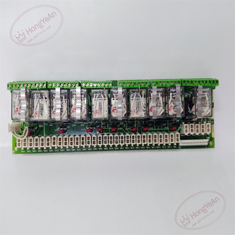
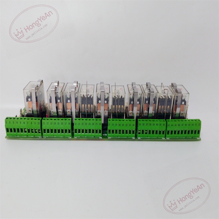
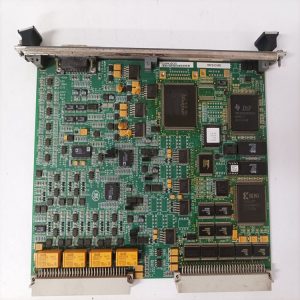
‑ Model: DS200RTBAG3AEB ‑ Part Number: DS200RTBAG3AEB ‑ Module Type: Mark‑V RTBA G3 Relay Trunk Terminal PCB Board ‑ Mounting: Screw‑fixed rack‑mount inside control cabinet ‑ Coil Power: 24 VDC from Mark‑V rack backplane ‑ Relay Configuration: • Total 10 relays • 7 × DPDT Form‑C contacts • 3 × 4PDT Form‑C multi‑pole contacts ‑ Contact Rating: Resistive load:2A@30VDC / 0.6A@125VAC; coil‑to‑contact isolation 1500V RMSDCSCPU ‑ Field Terminals: 52‑position screw‑type terminal block for field wiring ‑ Surge Protection: MOV metal‑oxide varistor for each relay channel ‑ Configuration components: Multiple Berg‑jumpers for signal‑path assignment; strictly duplicate original jumper positions during replacement ‑ Connectors: Dual stab‑type backplane connectors; multi‑pin ribbon‑cable connector; 52‑position field terminal block ‑ Diagnostics resources: Per‑channel relay‑status LED indicator lamps ‑ PCB treatment: Industrial conformal‑coated multilayer circuit board (‑AEB revision) ‑ Compatibility note: Exclusively for GE Speedtronic Mark‑V gas‑steam turbine, EX2000 excitation and DIRECTO‑MATIC2000 DC‑drive platforms; not drop‑in compatible with Mark‑VI / Mark‑VIe. After replacement, copy original jumper‑settings, verify stab‑connector full‑engagement, test each relay pull‑in action & LED status, measure dry‑contact continuity before applying field‑side load voltage.
Environmental Specifications
‑ Operating temperature: 0 ℃ ~ +60 ℃ ‑ Storage temperature: −40 ℃ ~ +85 ℃ ‑ Relative humidity: 5%‑95% non‑condensing ‑ Installation location: Indoor turbine‑control / drive cabinet, Pollution Degree 2, IP20 ‑ EMC compliance: Industrial EMC requirements for power‑generation turbine‑control‑room equipment ‑ Certifications: CE, UL compliant for power‑plant control‑system components
Mechanical Data
‑ Board dimension: approx 288 mm × 72 mm ‑ Mounting: Four‑point screw‑fixed cabinet rack‑mount ‑ Weight: approx 0.38 kg
Main Functions
- Provides 10‑channel isolated Form‑C dry‑contact relay outputs for Mark‑V system: implements turbine trip‑logic, permissive interlock, alarm relay output, excitation‑drive auxiliary interlock‑signal switching.
- 52‑position screw‑terminal block serves as field‑wiring termination point; dual stab‑backplane connectors receive drive‑commands from Mark‑V main CPU boards.
- MOV surge‑suppression components absorb field‑side voltage‑spikes, reduce contact‑arcing and extend relay service‑life. Hardware jumpers complete signal‑path assignment matching project‑specific I/O‑logic requirements.
- Per‑channel status‑LED lamps support daily monitoring, commissioning and field‑fault‑isolation troubleshooting.
Installation & Wiring Requirements
- Cut off rack 24VDC control power before installation or replacement. Non‑hot‑swappable. ESD wrist‑strap protection is mandatory during board handling.
- Secure DS200RTBAG3AEB onto cabinet rack. Reproduce jumper‑configuration exactly consistent with original‑board hardware settings. Guarantee dual stab‑backplane connectors fully seated; tighten all field‑terminal‑block wiring.
- All field‑wiring must strictly follow Mark‑V system‑wiring drawings. Reliable protective‑earth connection for control cabinet is mandatory.
- After replacement: Restore rack control‑power. Verify each relay‑channel pull‑in action and corresponding status‑LED indication. Measure dry‑contact‑continuity for every output channel. Complete static‑logic‑verification test before putting turbine‑unit into service.
- Replacement note: Incorrect jumper‑configuration, poor stab‑connector contact or loose field‑terminals will cause relay‑mis‑operation, loss of trip / permissive‑logic function, which may lead to unit‑trip‑events. Full‑system relay‑logic function verification test is mandatory before turbine‑unit commissioning.
Reviews
There are no reviews yet.