Description
Hardware & Electrical Specifications
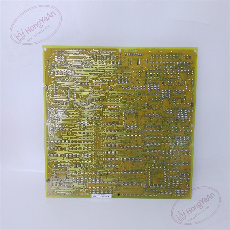
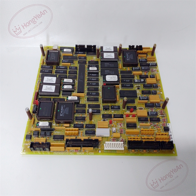
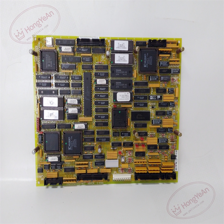
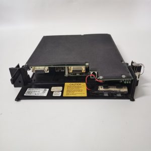
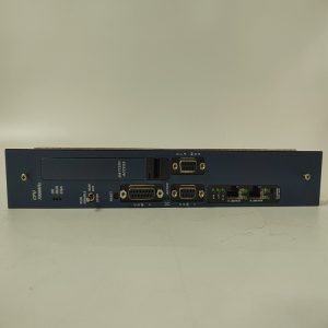
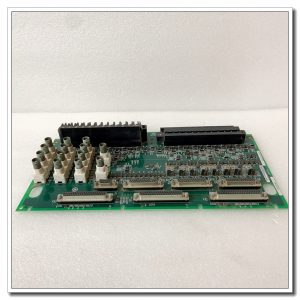
‑ Model: DS200SDCCG1AEC ‑ Part Number: DS200SDCCG1AEC ‑ Module Type: Mark‑V EX2000 / DM2000 SDCC Drive‑Control VME PCB Board ‑ Mounting: Standard 6U VME slide‑in rack‑mount with front‑panel ejector latches ‑ Power supply: +5 VDC, ±15 VDC supplied from VME backplane; typical power consumption approx 7‑10 W ‑ On‑board Processors: 3‑microprocessor parallel‑processing architecture for drive real‑time algorithm ‑ Memory: Flash‑PROM for firmware program; multi‑access shared RAM for high‑speed data exchange ‑ Configuration components: Multiple Berg‑style jumpers for drive‑mode, address and signal‑path assignment; partial jumpers reserved for factory test only ‑ Connectors: Dual rear VME backplane connectors; multi‑pin field‑signal ribbon‑cable interfaces ‑ Diagnostics resources: Front‑panel status‑fault LED array; large quantity of on‑board metal test‑point posts for waveform measurement ‑ PCB treatment: Industrial conformal‑coated multilayer circuit board (‑AEC revision) ‑ Compatibility note: Exclusively for GE Speedtronic Mark‑V gas‑steam turbine, EX2000 generator‑excitation and DIRECTO‑MATIC2000 DC‑drive platforms; not drop‑in compatible with Mark‑VI / Mark‑VIe. After replacement, strictly duplicate original jumper‑configuration, guarantee dual VME‑backplane connectors fully engaged, confirm firmware version matches system requirement, verify signal waveforms via test‑points and validate drive closed‑loop regulation performance.
Environmental Specifications
‑ Operating temperature: 0 ℃ ~ +60 ℃ ‑ Storage temperature: −40 ℃ ~ +85 ℃ ‑ Relative humidity: 5%‑95% non‑condensing ‑ Installation location: Indoor turbine / drive control cabinet, Pollution Degree 2, IP20 ‑ EMC compliance: Industrial EMC requirements for power‑generation excitation‑drive equipment ‑ Certifications: CE, UL compliant for power‑plant control‑system components
Mechanical Data
‑ Board dimension: 233 mm × 160 mm (standard 6U VME form‑factor) ‑ Mounting: VME rack slide‑in assembly with front‑panel ejector latches ‑ Weight: approx 0.86 kg
Main Functions
- Three‑processor parallel‑computing hardware executes real‑time drive‑control algorithm for EX2000 excitation and DM2000 DC‑drives: collects analog feedback signals, completes SCR firing‑angle calculation, implements current‑loop / speed‑loop closed‑loop regulation.
- High‑speed bidirectional data‑exchange with LDCC main controller over VME backplane: receives drive‑set‑point commands, uploads real‑time process‑values, alarm‑fault‑codes and drive‑operating‑status information.
- Multiple hardware jumpers configure drive‑operating‑mode, rack‑address and signal‑channel assignment. Massive on‑board test‑point posts facilitate commissioning waveform‑measurement and field‑fault‑isolation troubleshooting; LED array indicates drive‑fault status intuitively.
- Flash‑PROM stores drive‑firmware program; shared RAM realizes high‑speed data interaction among multi‑processors.
Installation & Wiring Requirements
- Cut off rack low‑voltage control power AND high‑voltage excitation‑drive power before installation or replacement. Non‑hot‑swappable. ESD wrist‑strap protection is mandatory during board handling.
- Insert DS200SDCCG1AEC into target VME slot, push fully home to engage dual rear VME‑backplane connectors and lock front‑panel ejector latches. Reproduce jumper‑settings strictly consistent with original‑board hardware configuration, do not alter factory‑reserved test‑jumpers. Confirm all ribbon‑cable connectors fully mated.
- All signal‑cable wiring must strictly follow Mark‑V / EX2000 system‑wiring drawings. Reliable protective‑earth connection for drive cabinet is mandatory.
- After replacement: Restore rack low‑voltage control‑power only. Observe front‑panel LED power‑status and fault‑indication. Measure key signal waveforms via on‑board test‑points. Confirm normal communication with LDCC controller. Complete static‑signal‑verification test before applying high‑voltage drive‑power; validate excitation‑drive closed‑loop‑regulation performance.
- Replacement note: Incorrect jumper‑configuration, poor VME‑backplane contact or firmware‑version mismatch will cause communication‑failure, drive‑algorithm‑abnormality, excitation‑mis‑operation or unit‑trip‑events. Full‑system communication‑function, drive‑control‑loop and protection‑logic‑verification test is mandatory before putting excitation‑drive into service.
Reviews
There are no reviews yet.