Description
Hardware & Electrical Specifications
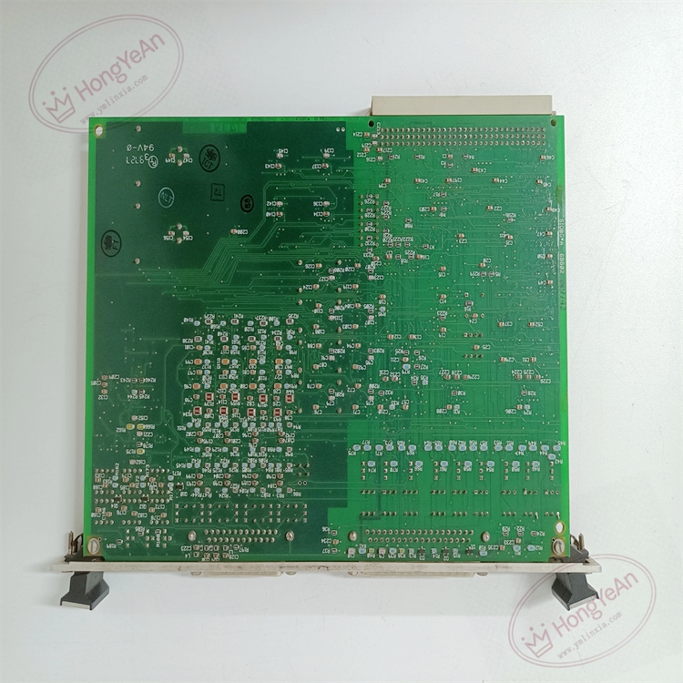
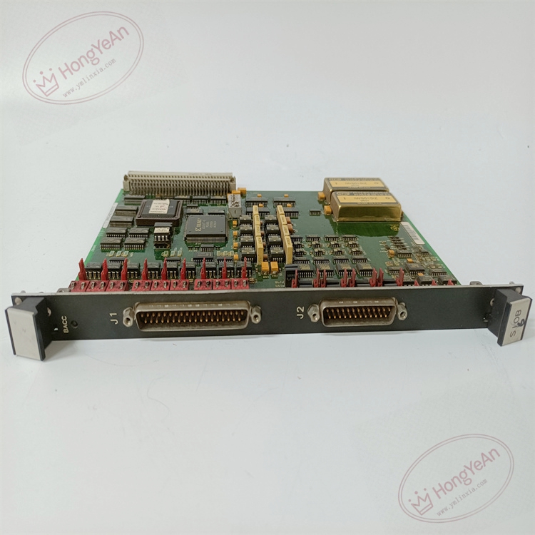
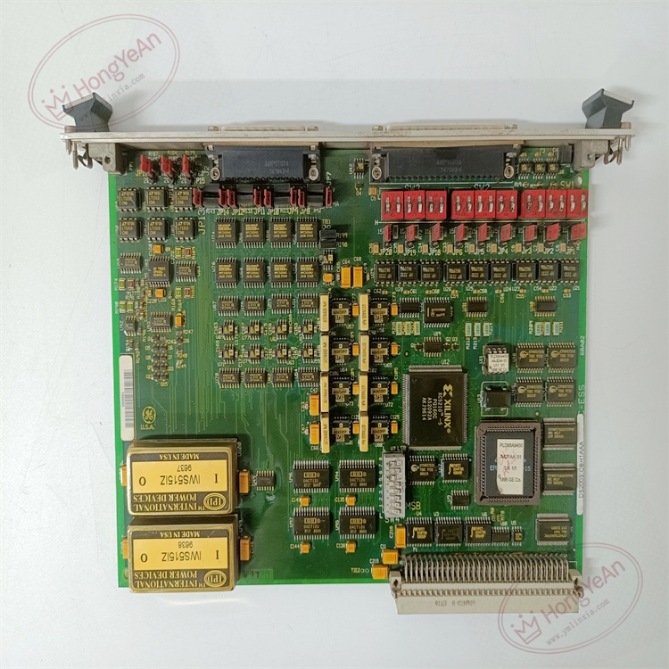
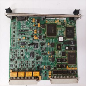
‑ Model: DS200SIOBH1AAA ‑ Part Number: DS200SIOBH1AAA ‑ Module Type: Mark‑V SIOB Servo Input‑Output VME PCB Board ‑ Mounting: Standard 6U VME slide‑in rack‑mount ‑ Logic Power: +5 VDC, ±15 VDC supplied from VME backplane ‑ Signal Interface: Servo command output; LVDT position feedback signal acquisition & conditioning ‑ Configuration components: 20 jumpers; 3×6‑position DIP‑switch blocks (18 switches total); must strictly copy original jumper & DIP‑switch positions during replacement ‑ Connectors: VME backplane connector; 40‑pin field‑wiring signal connector ‑ Diagnostics resources: Single status‑LED for board operational health indication ‑ PCB treatment: Industrial conformal‑coated multilayer circuit board (‑AAA revision) ‑ Compatibility note: Exclusively for GE Speedtronic Mark‑V gas‑steam turbine platforms; not drop‑in compatible with Mark‑VI / Mark‑VIe. After replacement, duplicate all jumper and DIP‑switch settings, verify VME backplane full‑engagement, check command‑output and LVDT feedback signal amplitudes before commissioning actuator loops.
Environmental Specifications
‑ Operating temperature: 0 ℃ ~ +60 ℃ ‑ Storage temperature: −40 ℃ ~ +85 ℃ ‑ Relative humidity: 5%‑95% non‑condensing ‑ Installation location: Indoor turbine‑control cabinet, Pollution Degree 2, IP20 ‑ EMC compliance: Industrial EMC requirements for power‑generation turbine‑control‑room equipment ‑ Certifications: CE, UL compliant for power‑plant control‑system components
Mechanical Data
‑ Board dimension: 233 mm × 160 mm (standard 6U VME form‑factor) ‑ Mounting: VME rack slide‑in assembly with front‑panel ejector latches ‑ Weight: approx 0.32 kg
Main Functions
- Servo‑actuator drive interface: receives valve‑position set‑point commands from Mark‑V main CPU over VME bus, outputs conditioned drive signals to field servo‑actuators (fuel valve, steam governor valve).
- LVDT feedback signal acquisition and conditioning: samples raw LVDT position‑feedback from actuators, converts to scaled analog‑digital values, feeds back to CPU for closed‑loop valve‑position regulation.
- Hardware‑mode configuration: 20 jumpers plus 18 DIP‑switches set channel assignment, LVDT gain, servo‑drive mode to match project‑specific actuator hardware parameters.
- On‑board status‑LED provides basic board‑health indication for commissioning and field troubleshooting.
Installation & Wiring Requirements
- Cut off rack control power before installation or replacement. Non‑hot‑swappable. ESD wrist‑strap protection is mandatory during board handling.
- Insert DS200SIOBH1AAA into target VME slot, push fully home to engage VME backplane connectors and lock front‑panel ejector latches. Reproduce jumper‑settings and DIP‑switch positions exactly consistent with original‑board hardware configuration. Secure the 40‑pin field‑signal connector.
- All field‑signal wiring must strictly follow Mark‑V system‑wiring drawings. Reliable protective‑earth connection for control cabinet is mandatory.
- After replacement: Restore rack control‑power. Observe board‑status‑LED state. Measure servo‑command output and LVDT feedback signal levels. Complete static‑loop‑verification test before putting valve‑actuator loops into service.
- Replacement note: Wrong jumper / DIP‑switch configuration or poor VME‑connector contact will cause position‑feedback errors, valve‑actuator mis‑operation, which may lead to turbine‑trip‑events. Full‑system servo‑loop function verification test is mandatory before turbine‑unit commissioning.
-300x300.jpg)
-1-1-300x300.jpg)
Reviews
There are no reviews yet.