Description
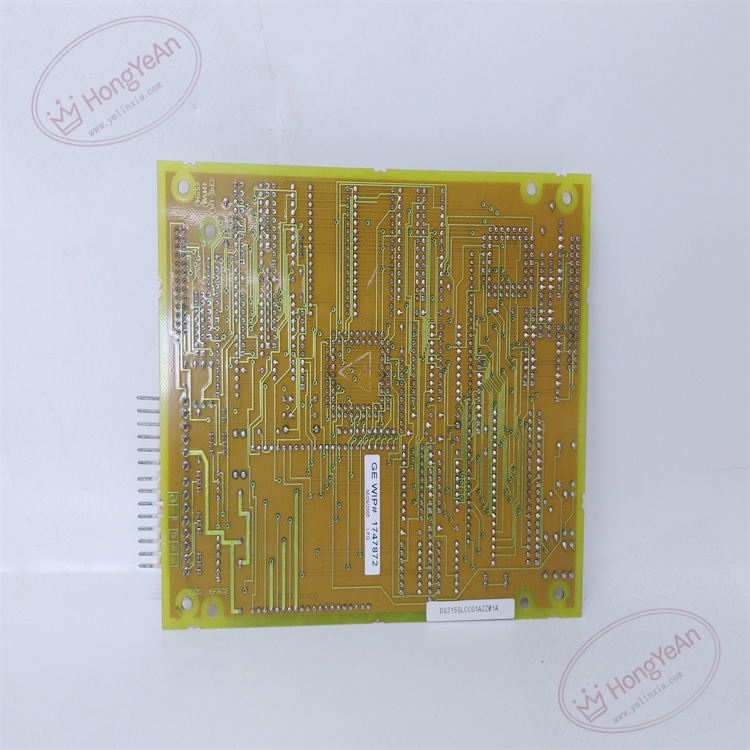
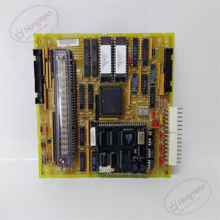
GE DS200SLCCG1ACC
Full Product Name: GE‑General Electric DS200SLCCG1ACC Slot Logic Communication Card (SLCC) Part Number: DS200SLCCG1ACC
Product Description
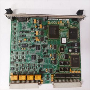
DS200SLCCG1ACC is a dedicated LAN communication auxiliary board for GE Speedtronic Mark‑V turbine & EX2000 excitation systems, suffix ‑ACC is conformal‑coated hardware revision. It mounts on the SDCC drive‑control board via bracket and KPPL ribbon connector, cannot work independently. It integrates LCP (LAN Control Processor), provides DLAN / ARCNET network interface, realizes data interaction between SDCC drive controller, operator keypad‑display, HMI and plant DCS system.
Critical note: This board does NOT contain operating firmware by default. Firmware is stored in two on‑board EPROM chips U6/U7; when replacing, you must transplant EPROM chips from original board, or procure pre‑programmed spare board.
Hardware resources: On‑board LCP processor, dual EPROM sockets for firmware storage, dual‑port shared RAM for SDCC data exchange, DLAN / ARCNET transceivers (isolated & non‑isolated circuit), keypad‑display interface, status LED indicators, configuration jumpers, KPPL multi‑pin ribbon‑cable connector. Obsolete legacy spare‑part, only refurbished / surplus available. Stack‑mount installation on SDCC board, non‑hot‑swappable. Reference manual: GEI‑100029.
Hardware & Electrical Specifications
‑ Model: DS200SLCCG1ACC ‑ Part Number: DS200SLCCG1ACC ‑ Module Type: Mark‑V SLCC LAN Communication Auxiliary PCB Board ‑ Mounting: Stack‑on‑SDCC bracket mounting ‑ Logic Power: +5 VDC, ±15 VDC supplied from SDCC board via KPPL connector ‑ On‑board Processor: LCP LAN control processor ‑ Memory: Two EPROM sockets for firmware; dual‑port RAM for high‑speed data exchange with SDCC ‑ Communication Interfaces: • DLAN (Drive Local Area Network) RS‑422, isolated / non‑isolated optional • ARCNET industrial network • Keypad‑display alphanumeric panel interface ‑ Configuration components: Berg‑style jumpers for DLAN isolation mode, termination resistor setting ‑ Connectors: KPPL ribbon‑cable connector to SDCC; network signal terminals; keypad‑display port ‑ Diagnostics resources: Multiple status‑LEDs for processor, network link, data‑activity indication ‑ PCB treatment: Industrial conformal‑coated multilayer circuit board (‑ACC revision) ‑ Compatibility note: Exclusively for GE Speedtronic Mark‑V gas‑steam turbine and EX2000 excitation platforms; NOT drop‑in compatible with Mark‑VI / Mark‑VIe. After replacement, transplant original EPROM firmware chips, copy jumper‑settings, verify KPPL connector tightness, check network communication status before commissioning drive system.
Environmental Specifications
‑ Operating temperature: 0 ℃ ~ +60 ℃ ‑ Storage temperature: −40 ℃ ~ +85 ℃ ‑ Relative humidity: 5%‑95% non‑condensing ‑ Installation location: Indoor drive control cabinet, Pollution Degree 2, IP20 ‑ EMC compliance: Industrial EMC requirements for power‑generation excitation‑drive equipment ‑ Certifications: CE, UL compliant for power‑plant control‑system components
Mechanical Data
‑ Board dimension: approx 216 mm ×146 mm ‑ Mounting: Stack‑mount onto SDCC board by plastic standoffs ‑ Weight: approx 0.25 kg
Main Functions
- LAN communication processing LCP processor processes DLAN and ARCNET protocol packets. Realizes high‑speed data exchange between SDCC local drive controller and external HMI, operator panel, plant DCS system; transmits drive set‑point, operating‑status, fault‑alarm, diagnostic data bidirectionally. Supports jumper‑selectable isolated / non‑isolated RS‑422 DLAN communication to adapt different field anti‑interference requirements.
- Keypad‑display interface management Connects local alphanumeric keypad‑display panel, completes man‑machine interaction: parameter viewing, fault diagnosis, drive‑parameter local modification, status‑text display.
- Data‑exchange with SDCC controller Through dual‑port shared RAM, completes high‑speed real‑time data interaction with host SDCC board; separates drive closed‑loop calculation task and network communication task, reduces SDCC processor load.
- Communication fault diagnosis & status indication On‑board LEDs indicate processor running state, network link status, data‑transmission activity. Detect communication link failure, report network‑fault status word to SDCC controller. Hardware jumpers configure network termination resistor, DLAN isolation mode.
Installation & Wiring Requirements
- Cut off rack control power before installation or replacement. Non‑hot‑swappable. ESD wrist‑strap protection is mandatory during board handling.
- Transfer U6, U7 EPROM firmware chips from original SLCC board to new DS200SLCCG1ACC board. Reproduce jumper‑configuration exactly consistent with original‑board hardware settings. Fix SLCC board onto SDCC bracket with standoffs, fasten KPPL ribbon‑cable connector firmly.
- All network‑signal wiring must strictly follow Mark‑V / EX2000 system‑wiring drawings. Reliable protective‑earth connection for control cabinet is mandatory.
- After replacement: Restore rack control‑power. Observe SLCC board status‑LEDs. Verify keypad‑display normal display, DLAN / ARCNET network link status. Confirm normal data interaction between SDCC, keypad‑panel and upper‑level system. Complete communication‑loop verification test before putting drive‑system into service.
- Replacement note: Missing or mismatched EPROM firmware, wrong‑jumper‑configuration or poor KPPL connector contact will cause communication failure, loss of local panel function, cannot upload drive operating‑data, may lead to drive‑system abnormal trip events. Firmware consistency check and full‑communication‑function verification test is mandatory before commissioning.
-1-1-300x300.jpg)
Reviews
There are no reviews yet.