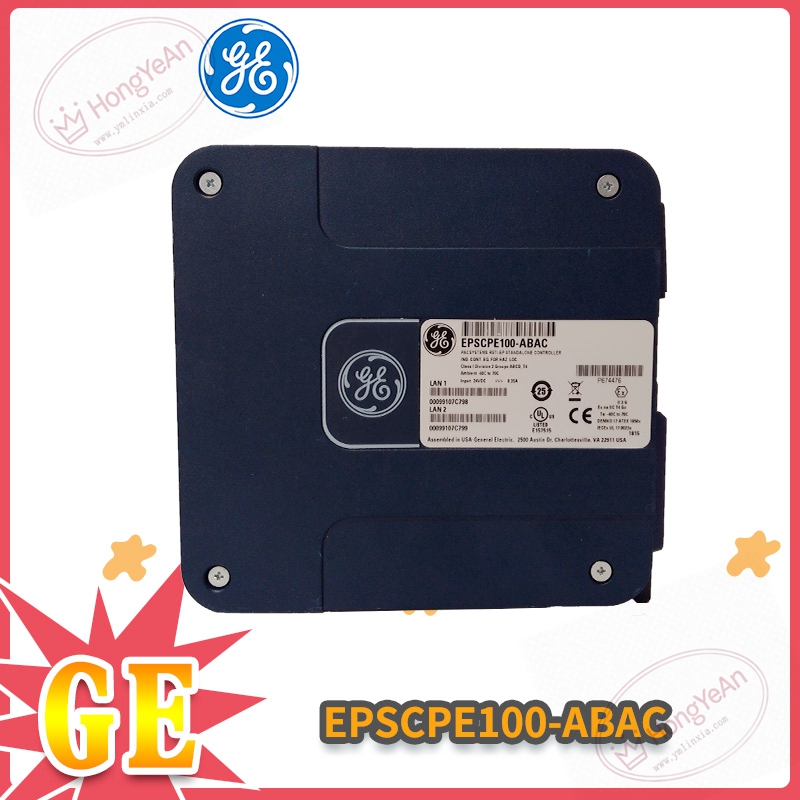
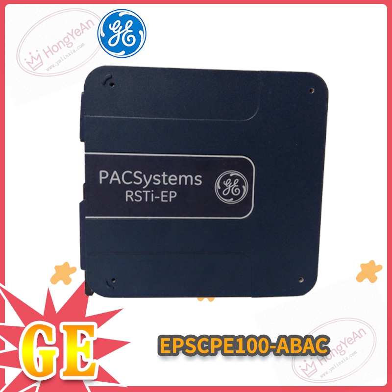
Description
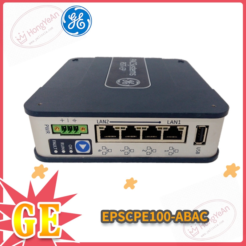
Physical appearance
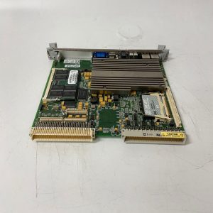
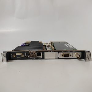
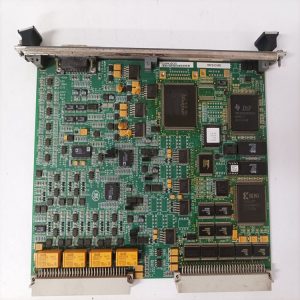
Common rack‑mount PCB circuit card with metal frame. ‑ Front panel: indicator LED lamps for power running status, system fault and communication alarm; simple locking clip for rack installation. ‑ Rear side: gold‑finger contacts for back‑plane power supply and internal bus data exchange. ‑ Several Harting‑style connectors on front section for external I/O signal wiring. ‑ PCB surface label marks full part‑number EPSCPE100‑ABAC. ‑ No independent metal housing, directly inserted into standard rack slot.
Core practical capabilities
Onboard CPU completes cycle logic calculation, collects DI/AI channel data and sends DO/AO output commands. Supports serial communication for parameter downloading and real‑time data upload. Parameter storage relies on onboard battery‑backed memory. Built‑in hardware watchdog for system fault self‑reset. Self‑diagnosis functions can capture sensor breakage, bus interruption and module over‑range status. Operating condition: temperature 0‑65℃, only indoor cabinet installation, IP20 protection. Important note: hardware suffix ABAC corresponds to specific firmware version. Random replacement with different suffix variants will trigger configuration incompatibility.
Real‑world usage
Frequently seen in power plant auxiliary control cabinets and industrial site transformation projects. It acts as core logic unit for EPS series control racks. If this CPU card fails, the whole control rack will lose regulating capacity. After replacement, import original project configuration, verify firmware revision consistency, check each point reading and logic action test before putting into online operation.
Installation reminders
Power‑off operation is recommended for swapping this card, to avoid scratch and oxidation damage to gold‑finger contacts. Signal and power cables shall keep certain distance from high‑power cables, reduce electromagnetic noise leading to abnormal sampling. Check onboard backup battery status regularly. Aging battery will cause configuration loss after power cut. Keep cabinet well‑ventilated. Excessive temperature will accelerate component aging. Do not open PCB housing on‑site; replace whole unit for hardware damage.
Common troubleshooting
- All LED indicators stay dark after power‑on: Check rack back‑plane power supply value, re‑seat module firmly in slot.
- Cannot download configuration parameters: Confirm serial cable connection, baud‑rate setting, check whether module enters fault lock‑up mode.
- System reports CPU offline alarm: Clean dust on back‑plane contacts, confirm firmware version matches other cards in rack.
- Measurement value drift or logic mis‑action: Inspect onboard battery voltage; rule out surrounding strong interference sources.
Reviews
There are no reviews yet.