Description
Physical characteristics
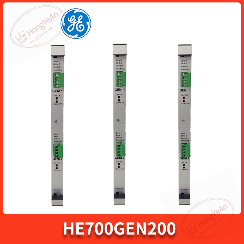
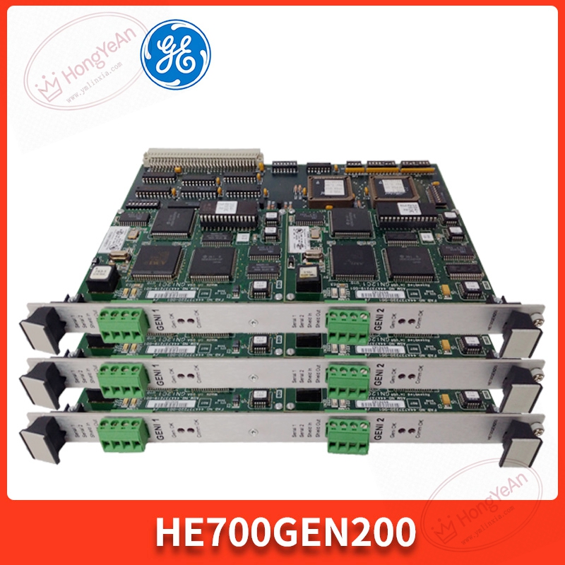
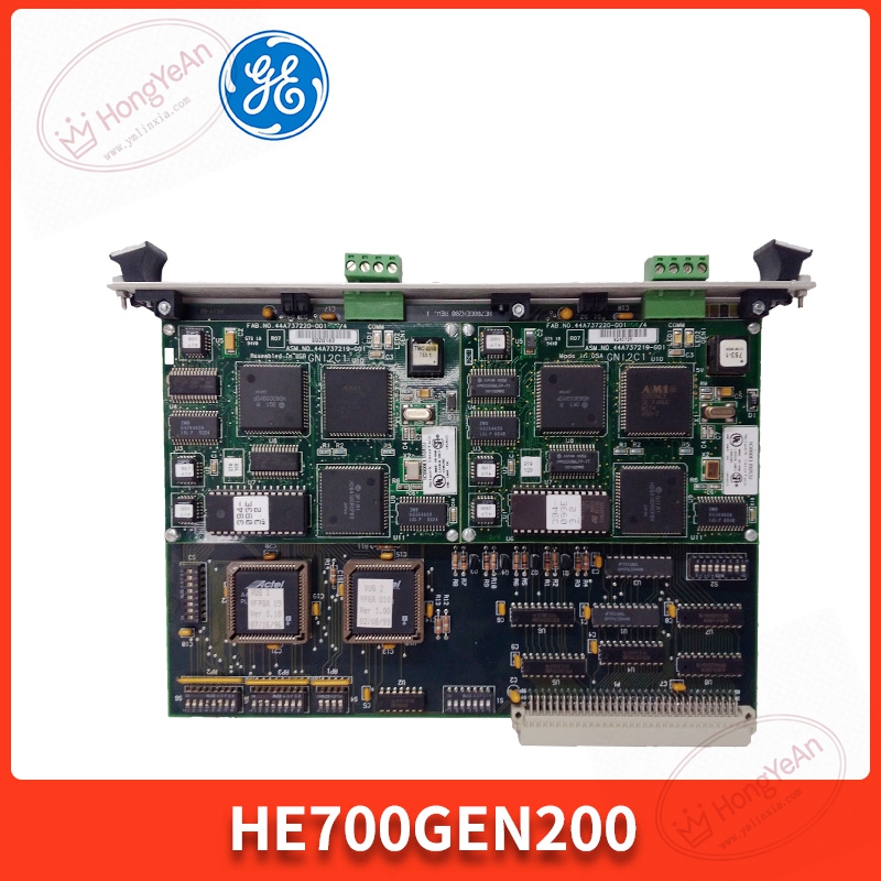
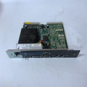
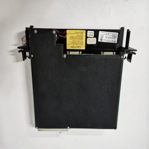
Standard VME 6U circuit card, fits common industrial cabinet rack slots. ‑ Front panel: status LED lamps for power, channel link and fault warning; spring locking clip for rack fastening; green screw terminal blocks for Genius bus wiring. Model sticker printed with HE700GEN200. ‑ Rear section: gold‑finger contacts, responsible for acquiring power and exchanging internal bus data with rack backplane. ‑ No separate metal shell, bare PCB board structure. On‑board DIP switches are used for station address and communication parameter setting.
Main working features
Dual independent Genius bus channels, supporting multi‑drop field I/O connection. Built‑in hardware diagnosis, can capture bus short‑circuit, signal break and communication abnormal information. Parameters are set via on‑board DIP toggle switches, no complicated software downloading required for basic debugging. Working environment: 0‑60℃ ambient temperature, cabinet‑internal installation only, IP20 protection grade. It should be noted that this board needs to match the firmware version of the host rack; inconsistent versions will lead to unstable bus transmission.
On‑site practical scenario
Frequently seen in factory production lines and energy‑industry control cabinets. It connects central control hardware with remote Genius‑series field I/O modules, completing collection of on‑site switching and analog signals. Once the board fails, the corresponding Genius bus segment will lose connection, field instrument data cannot upload to host system. After hardware replacement, adjust DIP switch parameters consistent with original settings, check bus link status and point‑by‑point signal reading before putting into actual operation.
Installation notes
Power‑off operation is preferred for board swapping, to avoid scratch and oxidation damage to gold‑finger contacts. Genius bus cables must adopt shielded type, keep proper distance from high‑power cables to reduce interference causing link flapping. Keep cabinet good ventilation; high temperature will accelerate aging of onboard chips. Do not disassemble PCB for component‑level repairing. Replace the whole circuit board when hardware damage occurs.
Common on‑site issues
- All indicators remain off after power‑on: Check rack back‑plane power supply, re‑insert the card firmly into slot.
- Genius bus communication drops frequently: Check bus terminal resistance setting, DIP‑switch address configuration, inspect cable aging condition.
- Partial field I/O points cannot be identified: Confirm whether the bus segment is overloaded, check for short‑circuit of field wiring.
- Module reports fault alarm: Clean dust on back‑plane contacts, verify firmware compatibility between board and rack CPU.
-1-300x300.jpg)
Reviews
There are no reviews yet.