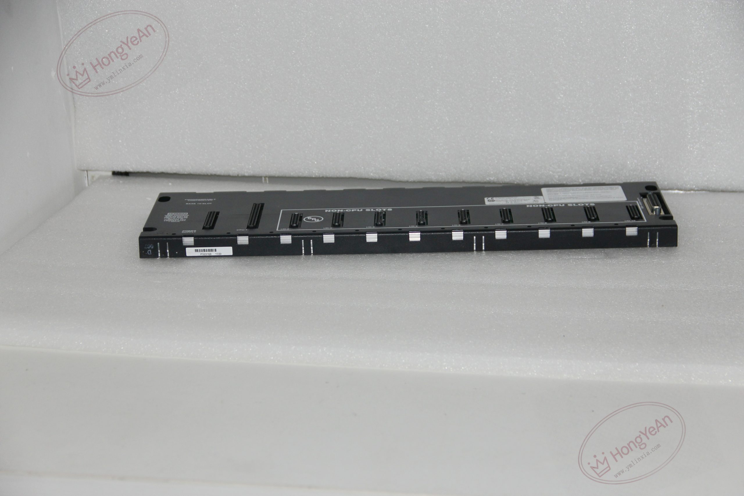
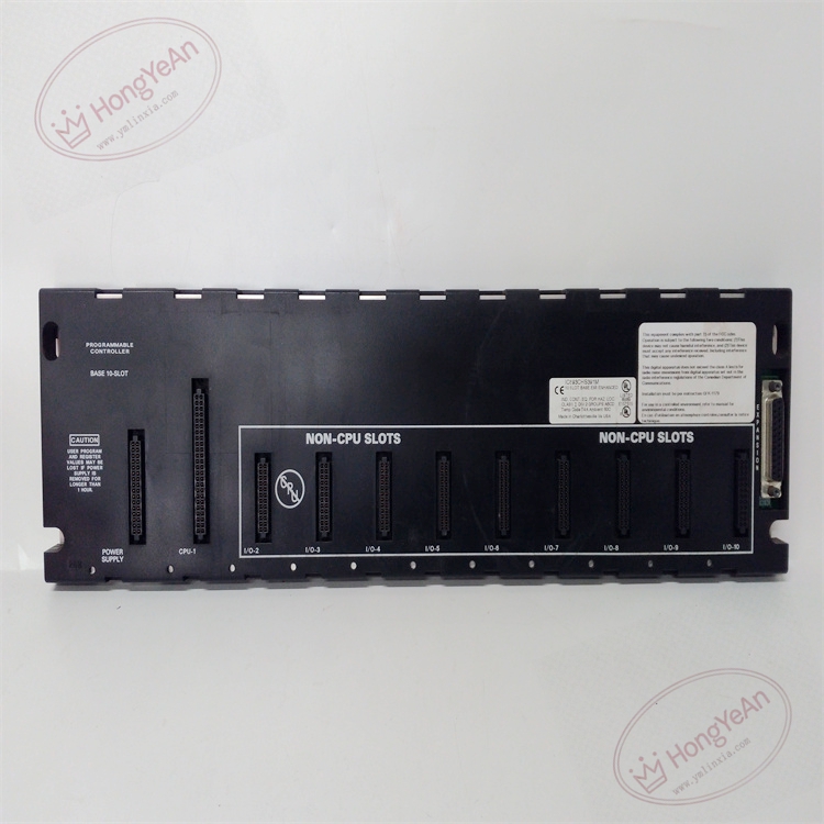
Description
Basic Hardware Information
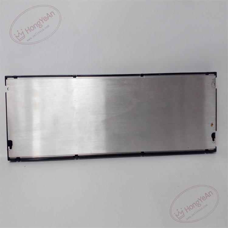
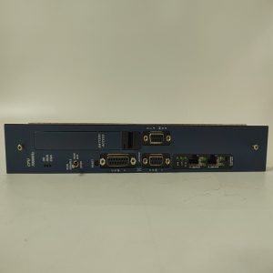
‑ Total slots: 10 slots total. Slot‑1 = dedicated CPU slot; slot‑0 = dedicated power‑supply slot; slots 2‑10 for I/O modules ‑ Backplane bus: Series 90‑30 parallel‑style I/O expansion bus ‑ Expansion interface: 25‑pin D‑Sub female connector (right side), for IC693CBL300 / IC693CBL314 expansion cables ‑ Max cumulative expansion‑chain length: 15 m; final expansion rack requires IC693ACC307 terminator plug ‑ Backplane rated current: 420 mA @5 VDC total for I/O modules ‑ Mechanical: DIN‑rail mount; metal housing with PCB backplane; weight approx 3 kg ‑ Operating ambient temperature: 0 ℃ ~ +60 ℃; storage temperature‑40 ℃ ~ +85 ℃; relative humidity 5‑95 % non‑condensing ‑ Handling note: ESD‑sensitive; anti‑static wrist‑strap required during module insertion/removal ‑ Compatibility: Series 90‑30 CPU & I/O modules only; incompatible with Series 90‑70 / VersaMax hardware.
Core Functions & Features
- Distributes 5 VDC backplane power and parallel bus signals to CPU, power‑supply and all plugged‑in I/O modules, coordinates register‑level data exchange across main‑rack modules.
- 25‑pin D‑Sub expansion port enables daisy‑chain connection to multiple expansion baseplates for I/O capacity expansion.
- Fixed slot assignment: power‑supply occupies far‑left slot, CPU must reside in slot‑1; physical slot position matches PLC hardware‑configuration slot addressing.
- DIN‑rail mechanical mounting provides vibration‑resistant installation for cabinet environment.
- Revision‑A/B units are direct drop‑in replacements for older IC693CHS391; no software configuration change required after replacement.
On‑site Installation & Commissioning Notes
- Power‑off entire PLC system before inserting / removing modules or expansion cables. Mount baseplate firmly on standard DIN‑rail inside control cabinet.
- Install power‑supply in left‑most slot, CPU module in slot‑1, populate remaining slots with corresponding I/O modules; press modules fully home until locking tab clicks.
- When building multi‑rack system: connect expansion‑cable from main‑rack D‑Sub port to first expansion‑baseplate. Fit IC693ACC307 terminator exclusively on D‑Sub port of last expansion rack in daisy‑chain. Tighten D‑Sub fixing‑screws. Route expansion‑bus cables away from high‑voltage power cables.
- Download hardware configuration to CPU, verify all main‑rack and expansion‑rack modules are recognized within programming software.
- Replacement note: Cannot substitute with expansion‑only baseplate (IC693CHS392). After baseplate replacement, double‑check module seating, expansion‑cable wiring and terminator location, perform full‑point I/O validation test.
Reviews
There are no reviews yet.