Description
Hardware & Electrical Specifications
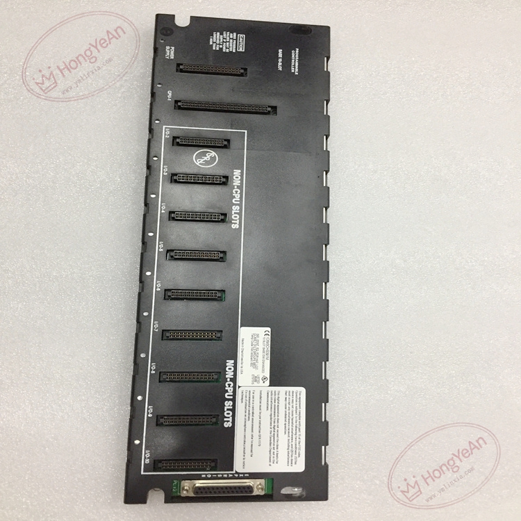
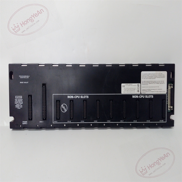
‑ Model:IC693CHS391 ‑ Part Number:IC693CHS391 ‑ Module Type:Series‑90‑30 10‑Slot CPU Main Baseplate ‑ Mounting:35 mm DIN‑rail or panel mounting ‑ Backplane bus:Parallel PLC backplane, 5 VDC logic power ‑ 5 VDC bus load capacity:420 mA maximum drawn from rack power supply ‑ Slot allocation: • Slot 1:Dedicated CPU slot • Slot 2‑10:9 slots for I/O, communication, motion and special‑function modules ‑ Power supply position:Independent un‑numbered slot on far‑left ‑ Expansion interface:25‑pin female D‑sub connector for expansion‑base cable ‑ Compatible power supply:IC693PWR321 / IC693PWR322 series power supply modules ‑ PCB treatment:Conformal coated for dust‑moisture‑corrosion resistance ‑ On‑board feature:Passive backplane, no active logic components; carries address and data bus signals between all plugged‑in modules ‑ Compatibility note:Cannot run standalone; must be fitted with valid power‑supply and Series‑90‑30 CPU module; total 5 VDC current consumption of all inserted modules must not exceed baseplate power budget; full rack bus continuity check mandatory after replacement。
Environmental Specifications
‑ Operating temperature:0 ℃ ~ +60 ℃ ‑ Storage temperature:‑40 ℃ ~ +85 ℃ ‑ Relative humidity:5%‑95% non‑condensing ‑ Installation location:Indoor industrial control cabinet, IP20 protection degree ‑ EMC compliance:IEC 61000‑6‑2 ‑ Certifications:CE, UL Class I Div 2 hazardous‑location certification
Mechanical Data
‑ Weight:approx 1.6 kg ‑ Dimension:443 × 130 × 142 mm (W × H × D) ‑ Handling note:ESD‑sensitive backplane connector contacts, anti‑static wrist‑strap mandatory during handling
Main Functions
- Main mechanical rack for Series‑90‑30 system, provides mounting slots for CPU, power‑supply, digital‑I/O, analog‑I/O, communication and motion modules.
- Realizes parallel backplane bus signal routing, completes high‑speed data communication between CPU and all plug‑in modules.
- 25‑pin expansion port supports connection to additional expansion baseplates to enlarge system I/O capacity.
Installation & Wiring Requirements
- Cut off all PLC rack power before replacement. Hot‑swap is forbidden. Strict anti‑static protection when handling baseplate.
- Secure IC693CHS391 onto DIN‑rail or control cabinet panel; install power‑supply module at left‑most position; insert CPU and each I/O/option module into respective slots and lock latches.
- If using expansion racks, connect dedicated GE expansion‑cable between 25‑pin port of main baseplate and expansion baseplate.
- Complete protective grounding according to GE Series‑90‑30 hardware manual specification.
- After replacement:power‑on rack, verify CPU power‑on and self‑diagnosis status, download PLC hardware configuration, test all local and expansion‑rack module communication.
- Replacement note: Calculate total 5 VDC current consumption of all modules to avoid power‑supply overload; verify CPU supports configured total rack quantity; full system commissioning test mandatory before unit put‑into‑service.
-1-1-300x300.jpg)
Reviews
There are no reviews yet.