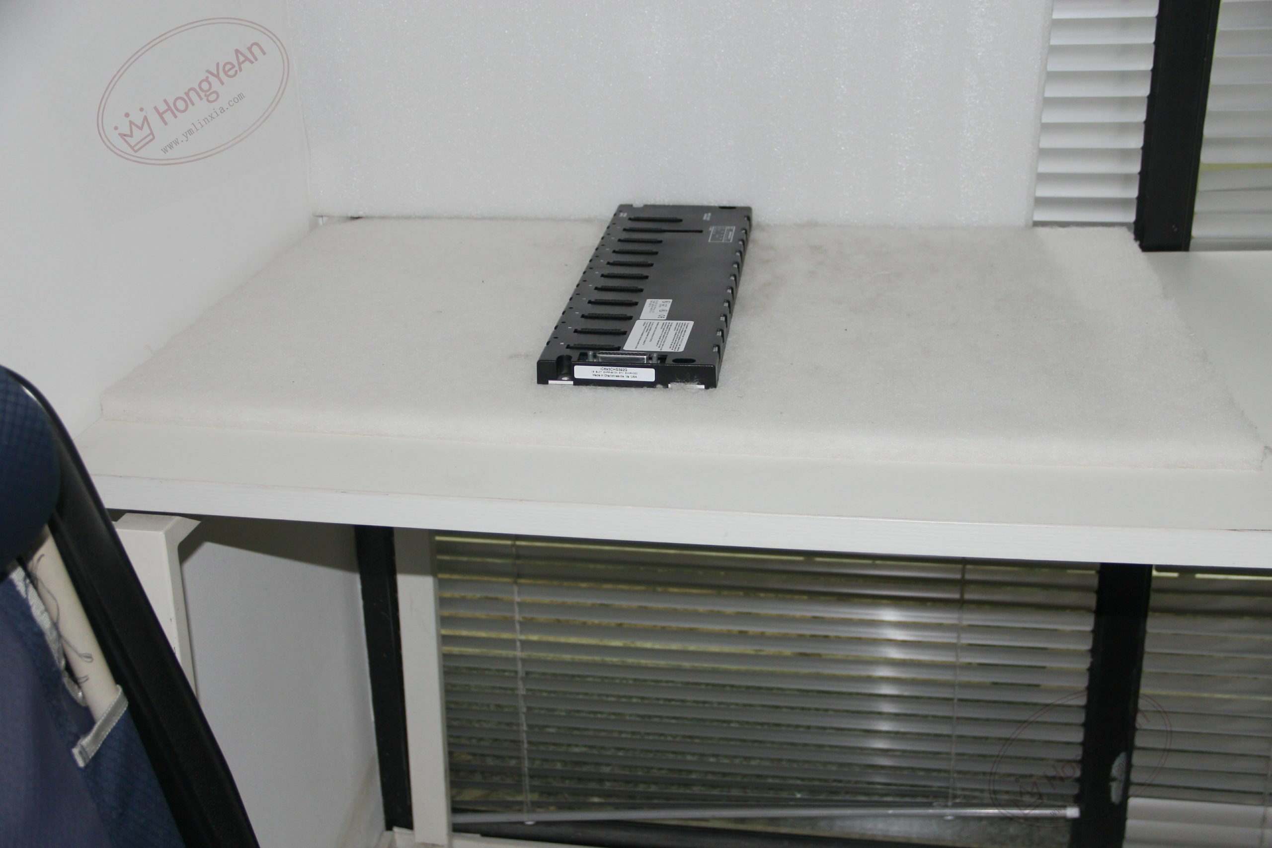
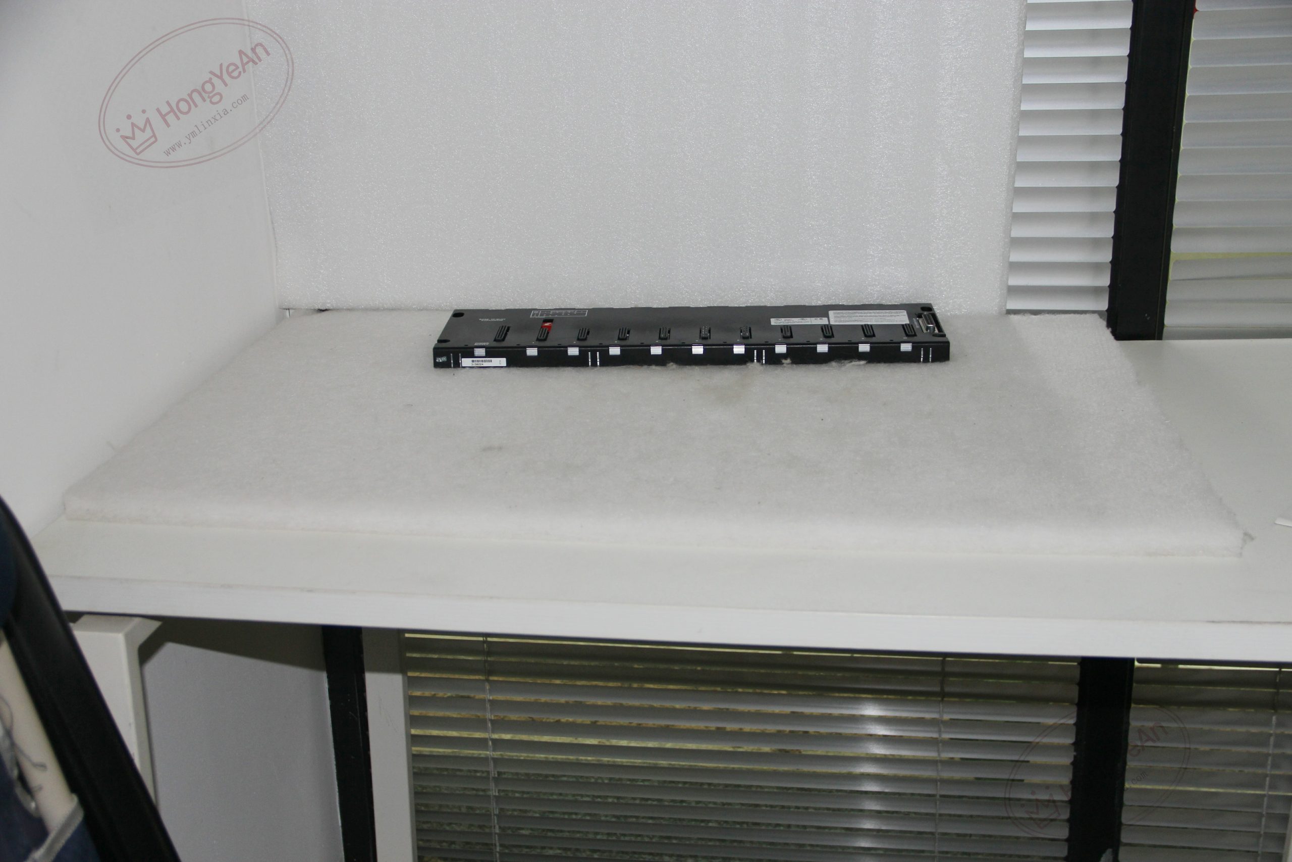
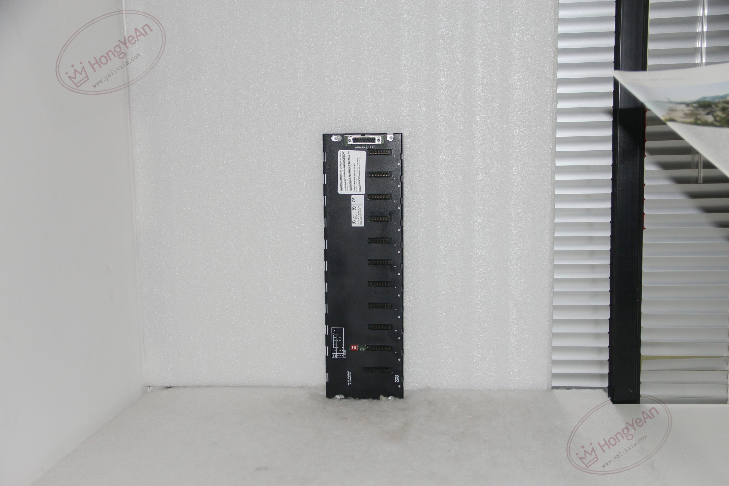
Description
Basic Hardware Information
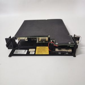
‑ Total slots: 10 slots; far‑left slot for power‑supply; no dedicated CPU slot; slots 1‑9 for I/O modules ‑ Backplane bus: Series 90‑30 parallel I/O expansion bus ‑ Expansion interface: 25‑pin D‑Sub female connector on right‑edge ‑ Rack identification: On‑board DIP switch for rack‑number setting ‑ Backplane self‑consumption: 150 mA @5 VDC ‑ Max total cumulative expansion‑cable length: 15 m; final rack requires IC693ACC307 terminator ‑ Mechanical: DIN‑rail mounting, metal frame + multilayer PCB backplane; weight approx 2.0‑2.5 kg ‑ Protection rating: IP20 (cabinet‑mount only) ‑ Operating ambient temperature: 0 ℃ ~ +60 ℃; storage temperature‑40 ℃ ~ +85 ℃; relative humidity 5‑95 % non‑condensing ‑ Limitation: Not compatible with intelligent communication option modules (BEM, CMM, PCM etc.) ‑ Handling note: ESD‑sensitive hardware; anti‑static wrist‑strap required during module insertion / removal ‑ Compatibility: Works with Series 90‑30 CPU system; cannot work standalone; incompatible with Series 90‑70 / VersaMax hardware。
Core Functions & Features
- Provides mechanical mounting, 5 VDC power distribution and parallel backplane‑bus signal interconnection for I/O modules in secondary expansion racks, expands total system I/O points, controlled by CPU residing on main IC693CHS391 baseplate.
- DIP‑switch rack‑number setting ensures PLC hardware configuration correctly distinguishes multiple expansion racks in daisy‑chain topology.
- Right‑side 25‑pin D‑Sub port supports multi‑stage daisy‑chaining of additional expansion baseplates.
- Local power‑supply module installed on this baseplate supplies backplane 5 VDC power for its own I/O modules; power is not delivered across expansion cable between racks.
- Revision‑J fixes known minor PCB errata from earlier hardware revisions; direct drop‑in replacement for IC693CHS392‑A/B/C/D/E/F/G/H; only rack‑number DIP‑switch needs verification after replacement, no software modification required.
On‑site Installation & Commissioning Notes
- Power‑off the whole Series 90‑30 PLC system before inserting / removing modules or expansion‑bus cables. Secure baseplate firmly on standard cabinet DIN‑rail.
- Install power‑supply on far‑left slot; populate I/O modules into remaining slots, press modules fully until locking tab clicks. Set DIP‑switch rack‑number matching hardware‑configuration rack‑address.
- Daisy‑chain wiring: Connect expansion‑cable from upstream rack D‑Sub to this baseplate D‑Sub. Mount IC693ACC307 terminator plug only on D‑Sub of last expansion rack in full chain. Tighten D‑Sub shell fixing‑screws. Route expansion‑bus cables away from high‑voltage AC power cables.
- Complete multi‑rack hardware configuration within programming software, download configuration to CPU. Verify all main‑rack and expansion‑rack modules are recognized; monitor expansion‑bus fault diagnostic bits.
- Replacement note: Cannot substitute with CPU‑type main baseplate IC693CHS391 / IC693CHS391EG. After replacement, double‑check rack‑number DIP‑switch setting, power‑supply seating, expansion‑cable connection and terminator location; perform full‑point I/O validation test.
Common On‑site Abnormal Conditions
‑ All modules on expansion rack unrecognized: Wrong rack‑number DIP‑switch setting; poor expansion‑cable contact; missing / misplaced IC693ACC307 terminator; upstream rack communication failure. ‑ Partial module loss‑of‑communication: Poor module insertion; backplane PCB trace damage; bent / broken pins on 25‑pin D‑Sub connector. ‑ Intermittent I/O faults: Vibration‑induced loose D‑Sub connectors; excessive total expansion‑cable length; insufficient shielding‑grounding; industrial EMI interference. ‑ Expansion rack no backplane power: Local power‑supply failure or poor seating on baseplate; expansion‑cable does not transfer power between racks. ‑ Special intelligent module failure: Installing BEM / CMM series modules on IC693CHS392J will lead to module fault; these modules must be installed on CPU main‑baseplate.
-1-300x300.jpg)
Reviews
There are no reviews yet.