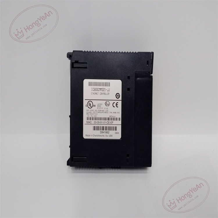
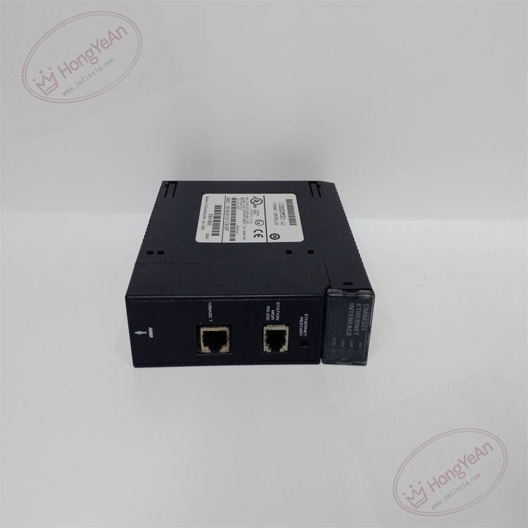
Description
Hardware & Electrical Specifications
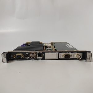
‑ Model:IC693CMM321 ‑ Part Number:IC693CMM321 ‑ Module Type:Series‑90‑30 TCP/IP Ethernet Communication Processor Module ‑ Mounting:Plug‑in onto Series‑90‑30 PLC backplane arbitrary I/O slot ‑ Backplane power:5 VDC @450 mA drawn from rack backplane ‑ Ethernet interface:1×RJ45, 10 Mbps 10Base‑T ‑ Supported protocols:SRTP server/client, Modbus‑TCP master/slave ‑ Max concurrent TCP connections:8 connections ‑ Modbus‑TCP default port:502 ‑ Station manager port:RJ‑11 RS‑232 serial debugging port for local IP address setting ‑ On‑board memory:64KB dual‑port RAM for backplane‑Ethernet data buffer ‑ PCB treatment:Conformal coated for dust‑moisture‑corrosion resistance ‑ On‑board protection:Hardware watchdog, network fault statistics, surge suppression ‑ Compatibility note:Cannot run standalone; match Series‑90‑30 CPU; firmware version shall match project configuration; full network communication test mandatory after replacement。
Environmental Specifications
‑ Operating temperature:0 ℃ ~ +60 ℃ ‑ Storage temperature:‑40 ℃ ~ +85 ℃ ‑ Relative humidity:5%‑95% non‑condensing ‑ Installation location:Indoor industrial control cabinet, IP20 ‑ EMC compliance:IEC 61000‑6‑2 ‑ Certifications:CE, UL Class I Div 2 hazardous‑location certification
Mechanical Data
‑ Weight:approx 0.32 kg ‑ Dimension:Series‑90‑30 standard single‑slot module form‑factor ‑ Handling note:ESD‑sensitive network circuit, anti‑static wrist‑strap mandatory during handling
Main Functions
- Independent TCP/IP Ethernet co‑processor, undertake Ethernet communication tasks without occupying PLC CPU scan resources.
- SRTP protocol: realize data read‑write between PLC and HMI, programming software, inter‑PLC data exchange.
- Modbus‑TCP master/slave function: realize interconnection with third‑party Modbus‑TCP instruments, drives and upper monitoring system.
- RJ‑11 debug port: local setting of IP address, subnet mask, gateway without Ethernet network.
- LED status indication: ‑ Green OK:Module power‑on and self‑test pass ‑ LAN:Ethernet physical link status indicator ‑ TX/RX:Network data sending/receiving activity indicator ‑ FAULT:Module hardware / network communication fault alarm
Installation & Wiring Requirements
- Cut off Series‑90‑30 PLC rack power before replacement. Hot‑swap is forbidden. Strict anti‑static protection when handling module.
- Insert IC693CMM321 fully into PLC backplane slot and lock latch.
- Use industrial shielded Ethernet cable for network wiring; separate network cables from high‑power cables; comply with industrial network wiring specification.
- Complete protective grounding according to GE hardware manual.
- After replacement: power‑on PLC, verify OK / LAN / FAULT LED status; set IP parameter via station‑manager port or software; download module configuration; perform Modbus‑TCP and SRTP communication test.
- Replacement note: Verify CPU firmware compatibility; pay attention to network isolation, the module has no built‑in network encryption authentication; full system communication commissioning test mandatory before unit put‑into‑service。
-1-1-300x300.jpg)
Reviews
There are no reviews yet.