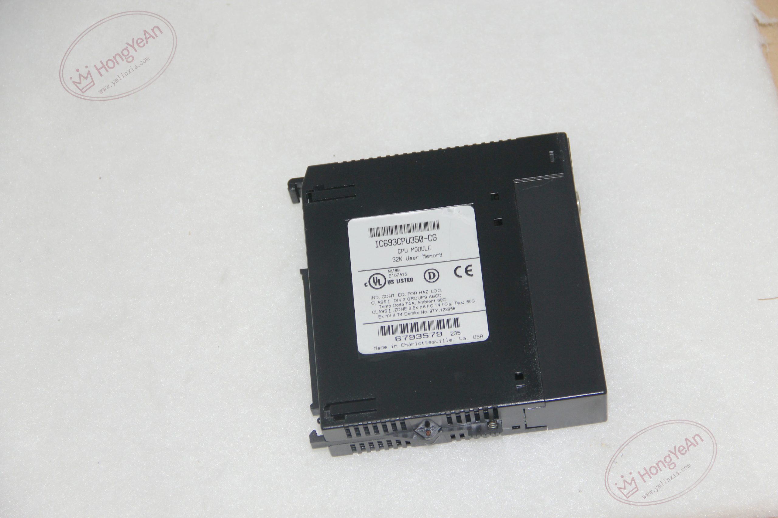
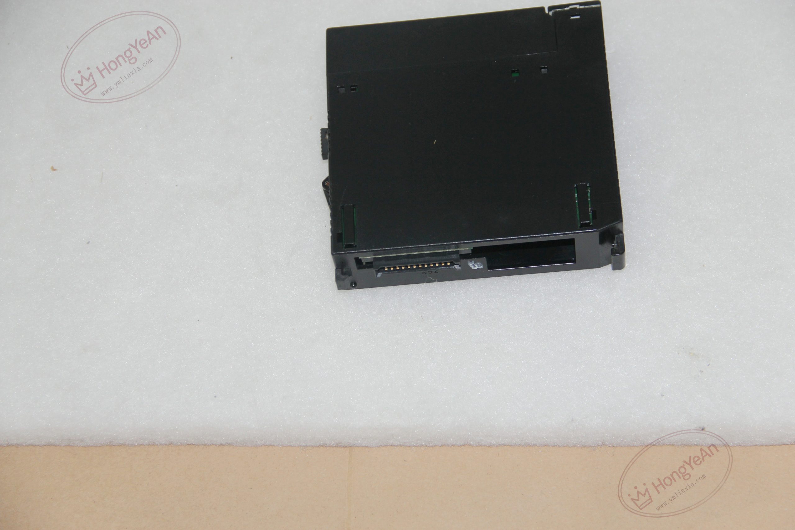
Description
Basic Hardware Information
‑ Processor: Intel 80386EX, 25 MHz ‑ Typical scan speed: 0.22 ms / 1K Boolean contacts ‑ User program memory: 32 KB flash memory ‑ Register memory (%R): 9999 words, battery‑backed ‑ Memory resources: %G 1280 bits; %M 4096 bits; %T 256 bits; %S system status bits ‑ Max I/O capacity: %I 2048; %Q 2048; %AI 2048 words; %AQ 512 words ‑ System rack limit: Max 8 racks (main + local / remote expansion) ‑ Communication: RS‑485 SNP/SNP‑X via power‑supply connector; additional communication realized via CMM / BEM option modules ‑ Real‑time clock: Yes, battery‑backed ‑ Back‑plane loading: 670 mA @5 VDC ‑ Mechanical: Standard single‑slot Series 90‑30 module; weight approx 0.3‑0.4 kg ‑ Operating ambient temperature: 0 ℃ ~ +60 ℃; storage temperature‑40 ℃ ~ +85 ℃; relative humidity 5‑95 % non‑condensing ‑ Handling note: ESD‑sensitive hardware; anti‑static wrist‑strap required during insertion / removal; battery aging will lose real‑time clock and register data ‑ Compatibility: Must be fitted in dedicated CPU slot of IC693CHS391 / IC693CHS397 main baseplate; cannot be installed on expansion‑only baseplates; compatible with full Series 90‑30 I/O and communication modules; incompatible with Series 90‑70 / RX3i hardware。
Core Functions & Features
- Executes ladder‑logic, function‑block and structured user program, handles discrete/analog I/O refresh, timer‑counter, floating‑point calculation, interrupt subroutine processing for medium‑size industrial control applications.
- Supports multi‑rack architecture: local parallel expansion via 25‑pin D‑Sub bus, also supports Genius remote I/O racks; total system up to 8 racks to expand I/O capacity.
- RS‑485 SNP‑X interface enables programming software upload/download and HMI/SCADA data access; additional Ethernet, Modbus‑TCP, Genius functions are implemented by plug‑in communication modules (CMM321, BEM331).
- Flash memory preserves user program after power loss; lithium backup battery maintains real‑time clock and %R register data during power‑off.
- Front‑panel multi‑LED indicates RUN, STOP, FAULT operating state; rich system status bits (%S) provide diagnostic information for user logic fault alarming.
- Different hardware‑firmware revisions are direct drop‑in replacements; after replacement, download PLC project and hardware configuration, verify battery status.
On‑site Installation & Commissioning Notes
- Power‑off complete PLC rack before inserting / removing CPU module. Insert CPU into slot‑1 of CPU‑main baseplate, press fully until locking tab clicks firmly. Confirm total 5 VDC back‑plane current budget of all modules does not exceed power‑supply rating.
- Complete multi‑rack hardware topology: local daisy‑chain expansion requires IC693ACC307 terminator plug on D‑Sub port of last expansion rack.
- SNP‑X serial communication: connect programming cable to power‑supply serial port; use shielded twisted‑pair and proper bus termination for multi‑drop network.
- Download hardware configuration and user program via programming software; switch CPU to RUN state; monitor %S system status bits for fault codes.
- Periodically inspect CPU backup‑battery; replace battery before depletion to prevent RTC time loss and register data corruption.
- Replacement note: Cannot install on expansion‑only baseplate IC693CHS392 / IC693CHS398. After replacement, verify slot‑1 installation, download project, test local & expansion‑rack I/O, check serial and option‑module communication.
-300x300.jpg)
Reviews
There are no reviews yet.