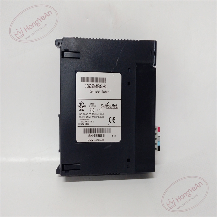
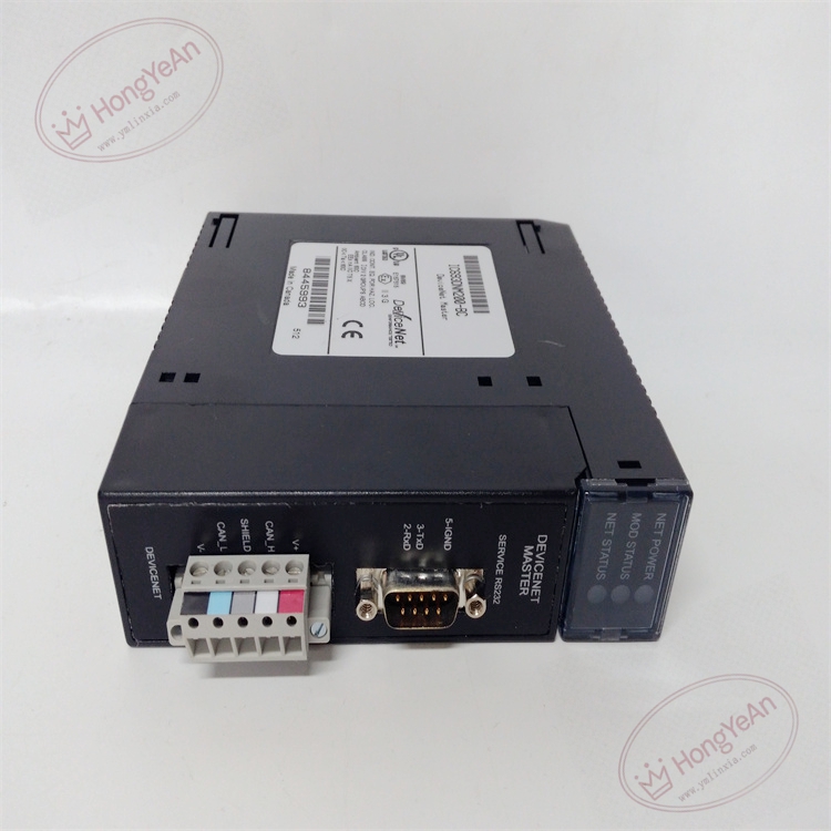
Description
Hardware & Electrical Specifications
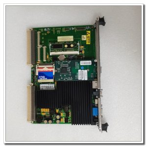
‑ Model:IC693DNM200‑BC ‑ Part Number:IC693DNM200‑BC ‑ Module Type:Series‑90‑30 DeviceNet Master Communication Module ‑ Mounting:Plug‑in onto any Series‑90‑30 PLC backplane I/O slot ‑ Backplane power:5 VDC @450 mA drawn from rack backplane ‑ DeviceNet baud‑rate:125 k / 250 k / 500 k baud, software configurable ‑ Max slave nodes:63 slaves per module; each slave supports max 2 I/O connections; total 126 I/O connections maximum ‑ Data buffer capacity:Per‑slave max 255‑byte input / 255‑byte output; global total max 3972‑byte input / 3972‑byte output ‑ Interfaces: • Removable spring screw terminal:DeviceNet bus connection • 9‑pin D‑sub female RS‑232 service port:firmware download, local debugging ‑ Supported connection types:Polled, Strobed, Cyclic, COS Change‑of‑State, UCMM explicit messaging, proxy connection per slave ‑ External bus power:DeviceNet bus power 12‑24 VDC supplied externally, not taken from PLC rack ‑ PCB treatment:Conformal coated for dust‑moisture‑corrosion resistance ‑ On‑board protection:Transient surge suppression on DeviceNet bus, hardware watchdog, network & slave diagnostic counter ‑ Compatibility note:Cannot run standalone; match Series‑90‑30 CPU; BC revision can directly replace AB version; DeviceNet trunk cable needs 121Ω terminating resistors at both ends; full DeviceNet network simulation test mandatory after replacement。
Environmental Specifications
‑ Operating temperature:0 ℃ ~ +60 ℃ ‑ Storage temperature:‑40 ℃ ~ +85 ℃ ‑ Relative humidity:5%‑95% non‑condensing ‑ Installation location:Indoor industrial control cabinet, IP20 ‑ EMC compliance:IEC 61000‑6‑2 ‑ Certifications:CE, UL Class I Div 2 hazardous‑location certification
Mechanical Data
‑ Weight:approx 0.34 kg ‑ Dimension:Series‑90‑30 standard single‑slot module form‑factor ‑ Handling note:ESD‑sensitive communication circuit, anti‑static wrist‑strap mandatory during handling; strictly comply with DeviceNet cabling specification
Main Functions
- Acts as DeviceNet network master for Series‑90‑30 PLC, manages bus scheduling, realizes bidirectional data exchange between PLC and field‑side DeviceNet slave devices.
- Supports multiple I/O connection modes and explicit message, completes real‑time acquisition and control for remote I/O, frequency converters, servo drives, field sensors and valve islands.
- Rich network diagnosis function: slave offline alarm, bus error statistics, communication fault status, upload fault information to PLC CPU.
- RS‑232 service port supports module firmware upgrade and local debugging without DeviceNet network.
- LED status indication on front panel: ‑ Green OK:Module power‑on and self‑test pass ‑ NET:DeviceNet network link status indicator ‑ I/O:Bus I/O data activity indicator ‑ FAULT:Module / network / slave fault alarm
Installation & Wiring Requirements
- Cut off Series‑90‑30 PLC rack power and DeviceNet external bus power before replacement. Hot‑swap is forbidden. Strict anti‑static protection when handling module.
- Insert IC693DNM200‑BC fully into PLC backplane slot and lock latch.
- DeviceNet field wiring strictly follow ODVA DeviceNet specification and GE hardware manual; use certified DeviceNet shielded cable; install 121Ω terminating resistor at both physical ends of trunk cable; separate bus cable from high‑power cables, connect shielding to protective ground terminal.
- Complete protective grounding according to GE system specification.
- After replacement:power‑on PLC and DeviceNet bus power; verify OK / NET / FAULT LED status; download DeviceNet hardware configuration; perform network scan, slave identification and full I/O communication test.
- Replacement note: Verify CPU firmware compatibility; BC revision fixes partial known bugs of AB version; confirm baud‑rate match and terminating resistor installation; full DeviceNet network commissioning test mandatory before unit put‑into‑service.
-1-1-300x300.jpg)
Reviews
There are no reviews yet.