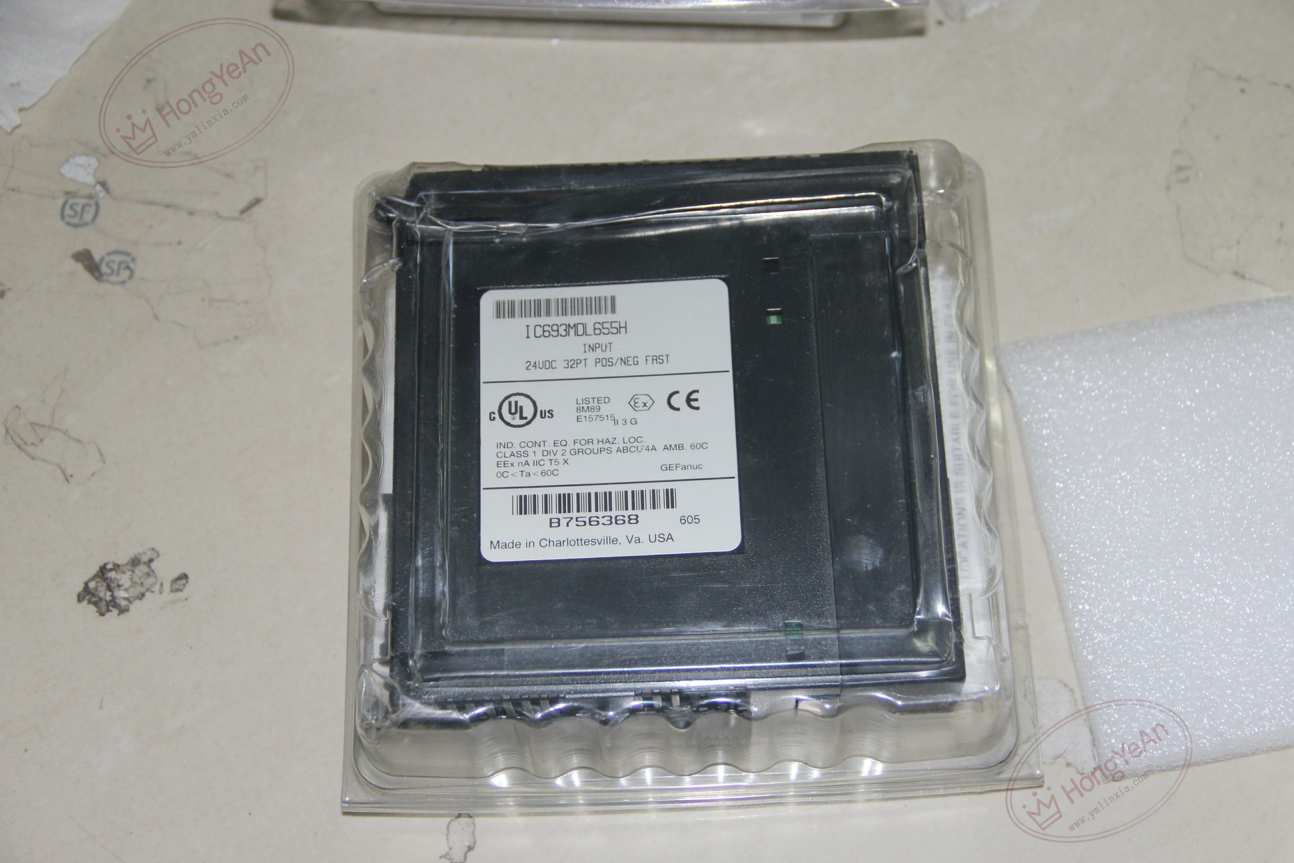
Description
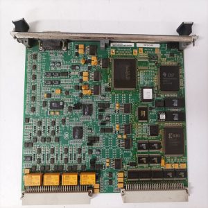
Hardware Specifications ‑ Slot usage: Single‑slot, fits any vacant slot on Series 90‑30 main / expansion baseplate ‑ Input channels: 32 points, 4 isolated groups × 8 points, independent common terminal per group ‑ Rated signal: 24 VDC, operating range 0‑30 VDC ‑ Logic threshold: ON ≥11.5 VDC; OFF ≤5 VDC; typical 7 mA per‑channel on‑state current ‑ Response time: 1 ms / 3 ms / 7 ms software configurable ON/OFF delay ‑ Isolation: 1500V RMS between field‑side and PLC backplane; 250V group‑to‑group isolation ‑ Backplane draw: 195 mA @5VDC ‑ Field connector: Two 24‑pin header connectors, compatible with IC693CBL327 / IC693CBL328 pre‑made cables ‑ Status indication: 32‑channel LED array for individual point status feedback ‑ Operating ambient: 0‑60℃, non‑condensing industrial cabinet installation
Core Functions Collects digital status from proximity sensors, limit switches and pulse‑type field devices, maps signals to PLC %I input memory table. Four isolated groups allow different field power supplies for separate process zones, reducing cross‑group interference. Adjustable input filter timing balances anti‑jitter performance and high‑speed signal capture requirements. Optocoupler isolation suppresses surge noise and ground‑loop disturbance; LED indicators simplify on‑site inspection.
Installation Requirements Secure the module latch after inserting into empty I/O slot of Series 90‑30 rack. Assign common‑terminal polarity for each group according to actual sensor wiring mode. Avoid mixing different‑voltage power sources to one input group; respect per‑group current limit. Use matched pre‑wired cables or properly terminated custom harness for front‑header connections. Separate signal wiring from high‑power cables; apply shielded twisted‑pair for long‑distance runs. Complete hardware configuration within programming software before power‑on commissioning.
Common Fault Modes ‑ Individual LED remains off: Missing field power, broken wire or defective field sensor ‑ Random channel flickering: Loose terminal connection, unstable 24VDC supply, heavy site EMI ‑ LED activates but PLC reads no input: Poor backplane contact, internal circuit damage ‑ Multiple‑group abnormal: Surge voltage destroys opto‑isolation components across groups ‑ Signal mis‑trigger: Improper response‑time setting, insufficient noise suppression on field wiring ‑ Connector‑related failure: Damaged header pins, incompatible mating cable assembly
Reviews
There are no reviews yet.