Description
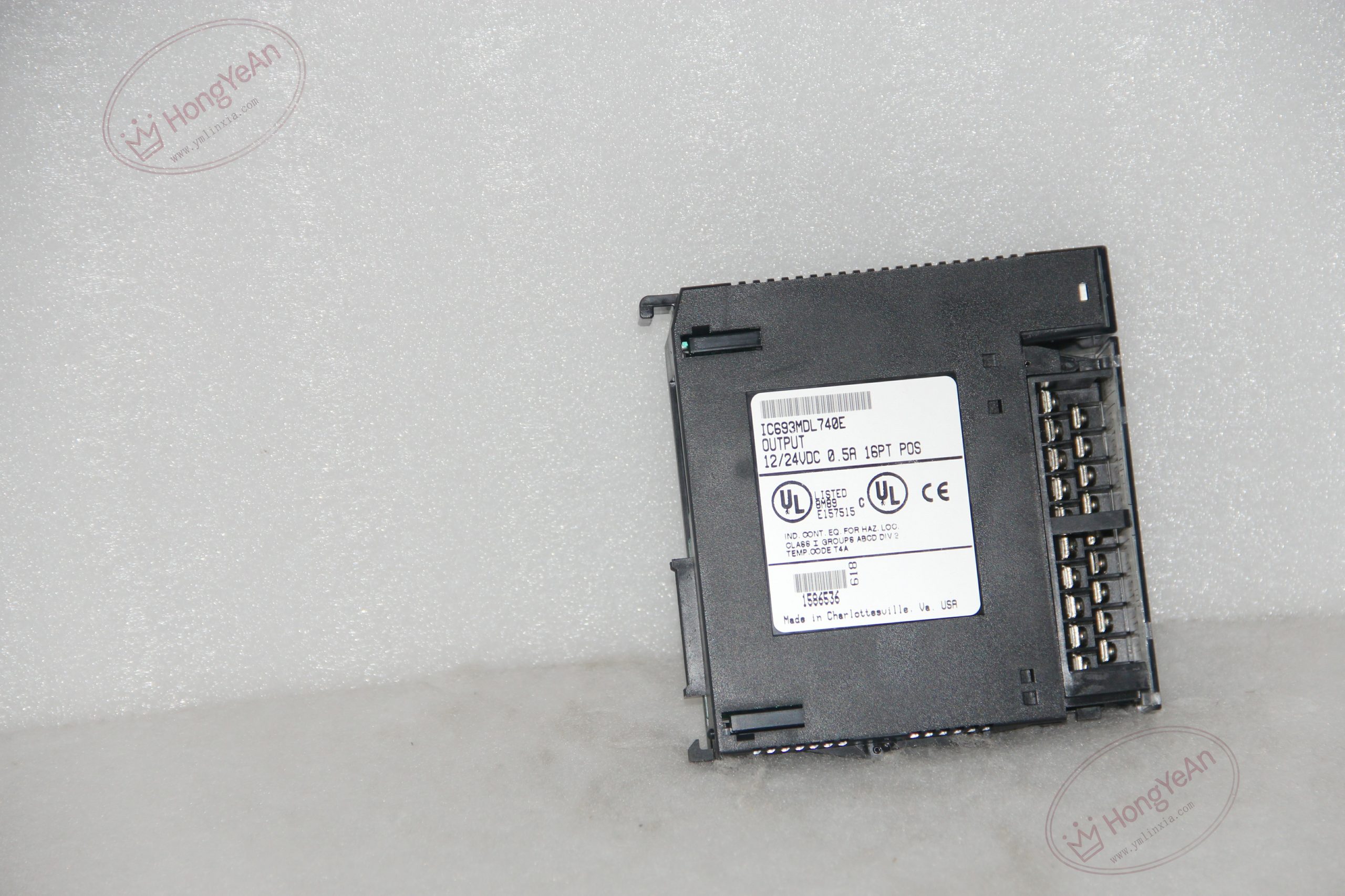
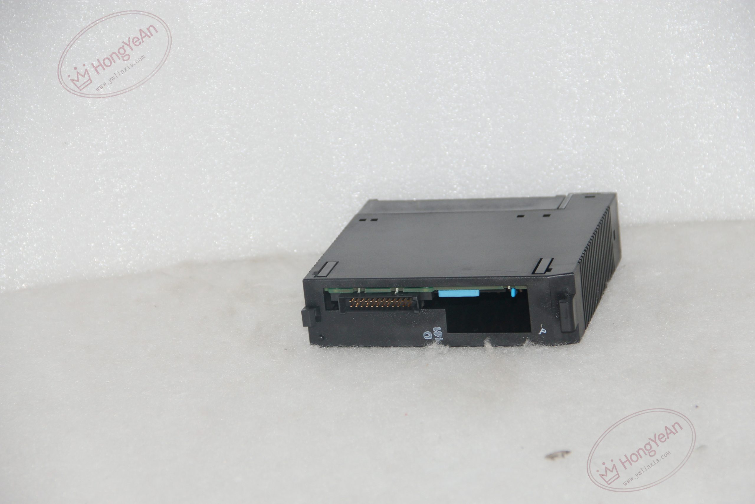
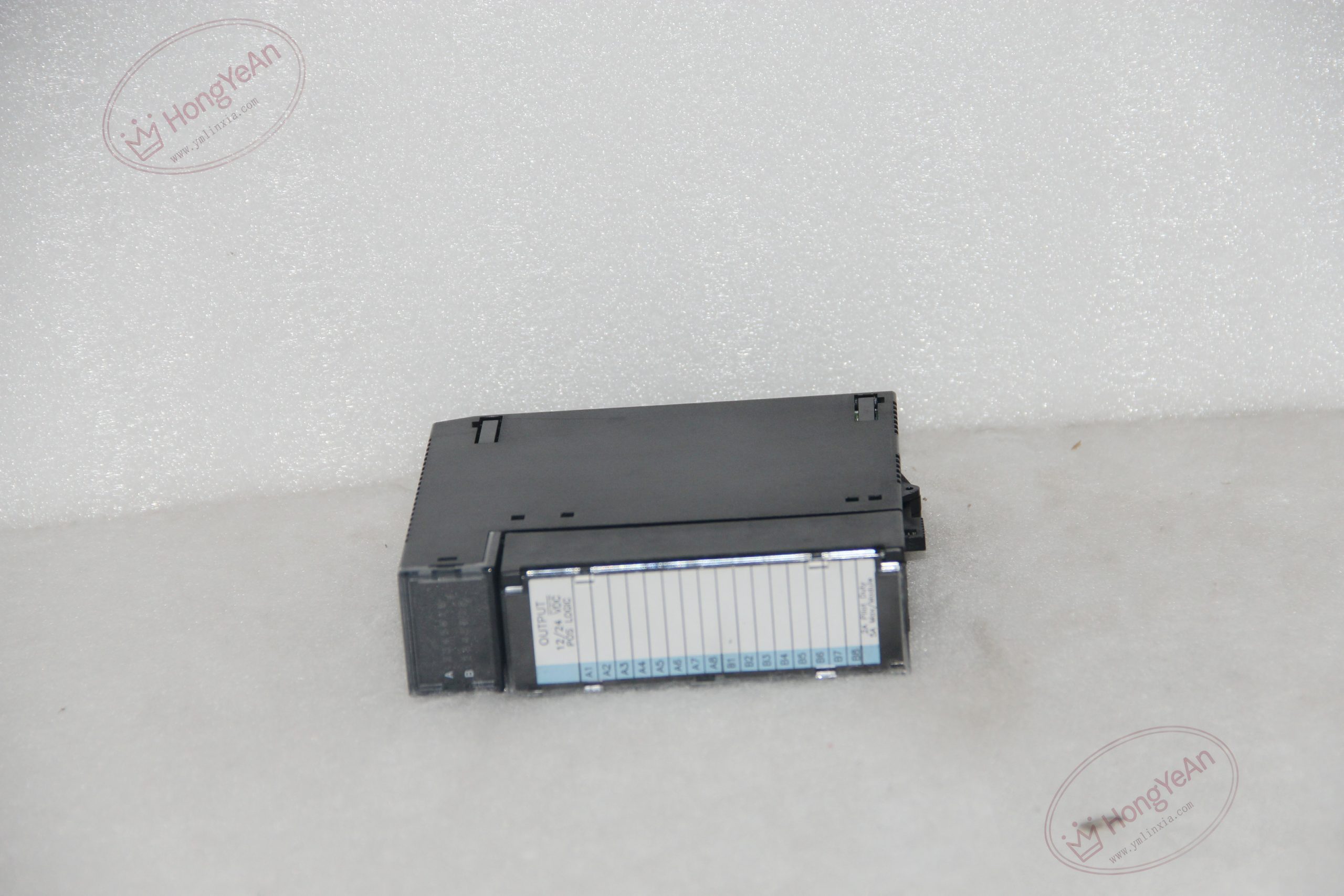
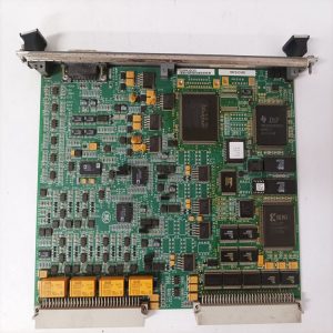
Hardware Specifications ‑ Slot requirement: Single‑slot, fits any vacant slot on Series 90‑30 main / expansion baseplate ‑ Output layout: 16‑point sourcing (positive logic), 2 isolated groups × 8 channels ‑ Load voltage: 12‑24VDC, tolerance +20% /‑15% ‑ Current rating: 0.5A per channel; 2A maximum per group; 4.78A 10ms inrush current ‑ Electrical parameters: Max 1V output drop; off‑state leakage ≤1mA; max 2ms ON/OFF response time ‑ Isolation: 1500V RMS field‑to‑logic isolation; 500V RMS group‑to‑group isolation ‑ Backplane load: 110mA @5VDC (all outputs activated) ‑ Status indicator: Dual‑row green LED array for point‑by‑point output status ‑ Operating ambient: 0‑60℃, non‑condensing industrial cabinet installation
Core Functions Converts PLC %Q register logic commands into sourcing‑mode 12‑24VDC drive signals for field actuators. Two independent groups allow separate external power supplies for different process zones. Optocoupler isolation blocks field‑side surge and noise, protecting PLC backplane circuits. Visual LED feedback supports quick on‑site commissioning and point‑level fault diagnosis.
Installation Requirements Secure module latch after inserting into empty I/O slot of Series 90‑30 rack. Supply external 12‑24VDC field power to each group’s common terminal; do not use rack auxiliary power for heavy loads. Respect per‑point 0.5A and per‑group 2A current limits to avoid over‑heating. Install free‑wheeling diodes for inductive loads to suppress coil back‑EMF. Separate DC output wiring from high‑power cables to reduce electromagnetic interference. Do not apply sinking‑mode load wiring without external circuit modification.
Common Fault Modes ‑ LED shows ON but load remains inactive: Open‑circuit field wiring, burnt‑out load device, insufficient external supply voltage ‑ Single channel burnout: Output terminal short‑circuit, missing flyback diode for inductive coils, over‑current stress ‑ Intermittent load actuation: Loose terminal connection, group over‑current, heavy site EMI disturbance ‑ Multiple‑group failure: Surge voltage damages internal opto‑coupler and switching components ‑ No reaction to PLC commands: Poor backplane contact, module hardware failure, incorrect output‑address mapping
-300x300.jpg)
Reviews
There are no reviews yet.