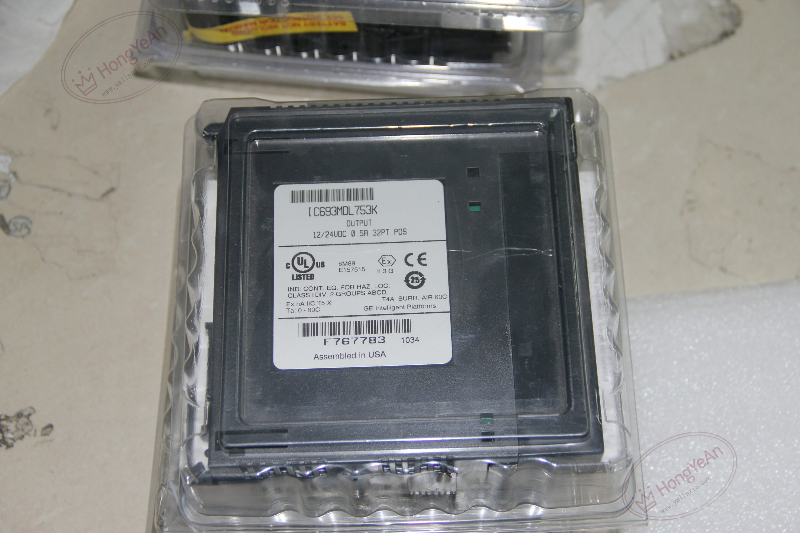
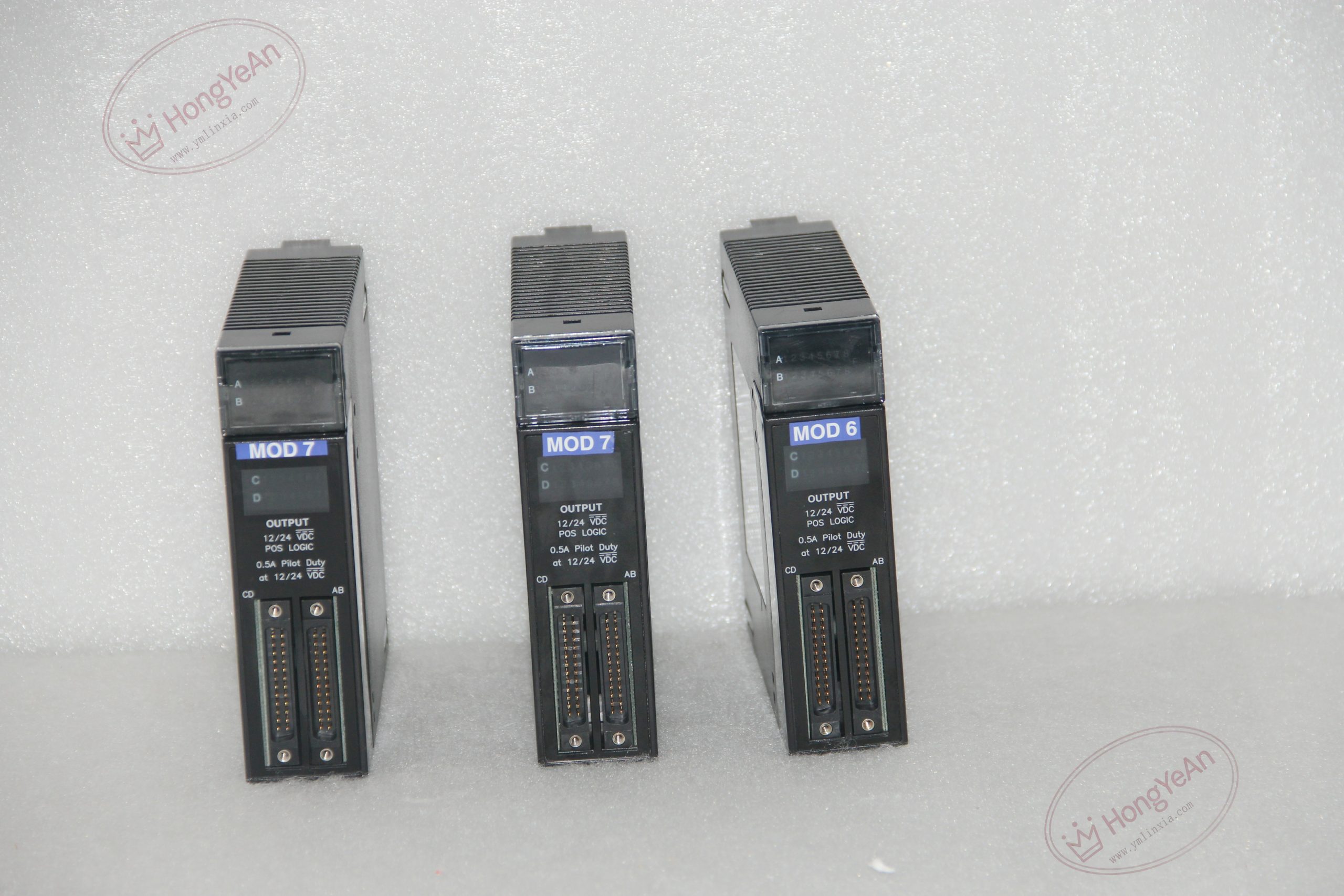
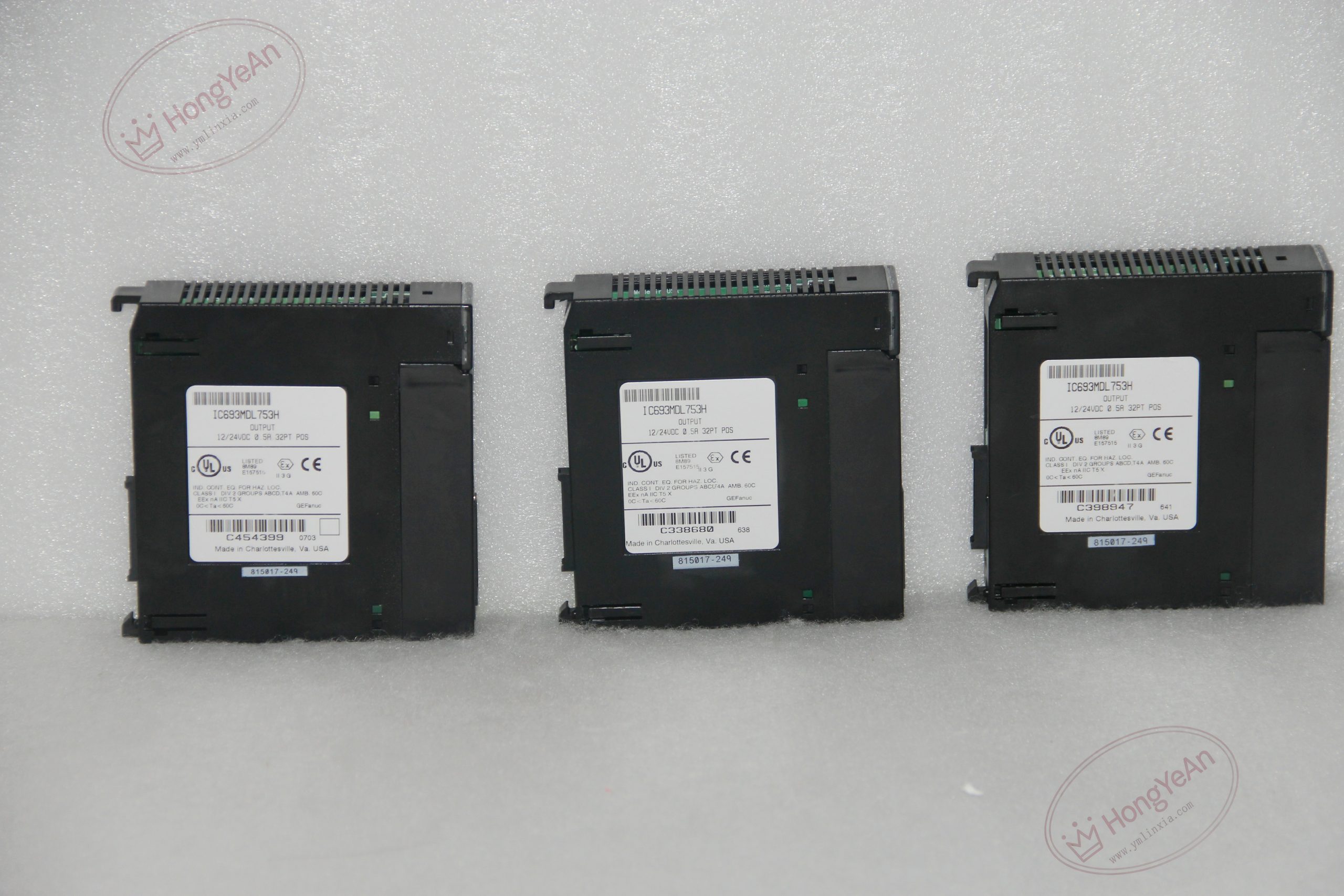
Description
Key Technical Parameters
- Channel layout: 32 sourcing outputs, split into 4 isolated groups (8 points per bank)
- Working voltage: 12‑24 VDC, operating tolerance 10.2‑28.8 VDC
- Current rating: 0.5 A per channel; max 4 A for each group
- Response performance: Typical 2 ms switching speed for ON‑OFF transitions
- Isolation specification: 1500 V RMS field‑to‑backplane isolation; group‑to‑group isolation 500 V RMS
- Backplane consumption: 180 mA @5 VDC under full‑load status
- Field connection: Dual 24‑pin header connectors, works with matched prefabricated cable assemblies
- Visual feedback: LED indicators corresponding to each output channel
- Operating range: 0‑60 °C, non‑condensing cabinet‑mount installation
Practical Application Features Four isolated banks allow separate external power sources for different process sections, lowering cross‑group interference risk. Optocoupler isolation protects PLC internal circuits against field‑side surge and noise interference. High‑density 32‑point design reduces rack‑slot occupation for systems requiring substantial digital output resources. Channel‑level LED status offers straightforward reference for on‑site commissioning and routine inspection.
Field Installation & Commissioning Notes Install the module into any vacant slot of Series 90‑30 main or expansion rack and lock the latch securely. Each group requires independent external 12‑24 VDC field power; avoid drawing load current from rack auxiliary power supply. Observe per‑point and per‑group current limits to prevent thermal overload. Inductive loads such as solenoid coils shall be fitted with free‑wheeling diodes to suppress back‑EMF. Separate field‑wiring paths from high‑power cables; shielded cables are recommended for long‑distance wiring scenarios. Complete hardware configuration inside programming software before system power‑on.
Real‑World Troubleshooting Reference
- LED indicates ON status but target actuator remains inactive: Inspect for open‑circuit wiring, burnt‑out load or insufficient external supply voltage.
- Single‑channel burnout: Usually caused by field‑terminal short‑circuit, missing flyback diode or sustained over‑current.
- Sporadic unstable action: Check loose terminal connections, over‑current across group, or heavy electromagnetic interference on‑site.
- Multiple‑bank malfunction: Surge voltage may damage internal optocoupler and switching components.
- No reaction to PLC logic commands: Investigate backplane contact condition, module hardware integrity and output address configuration.
-300x300.jpg)
Reviews
There are no reviews yet.