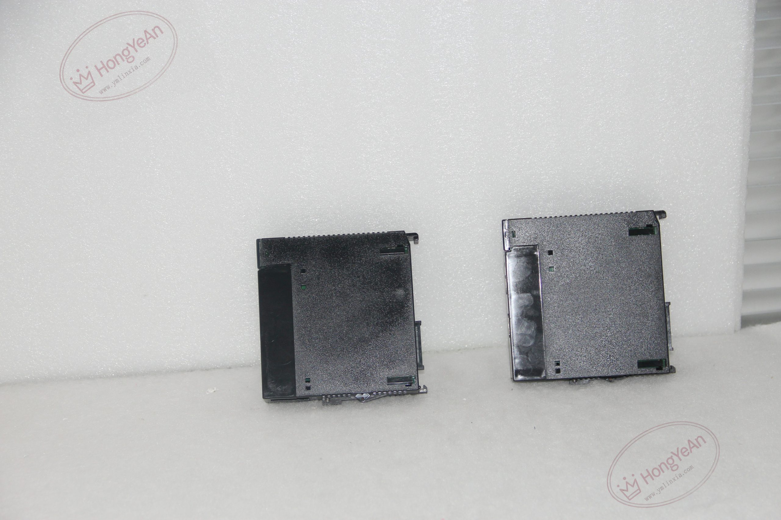
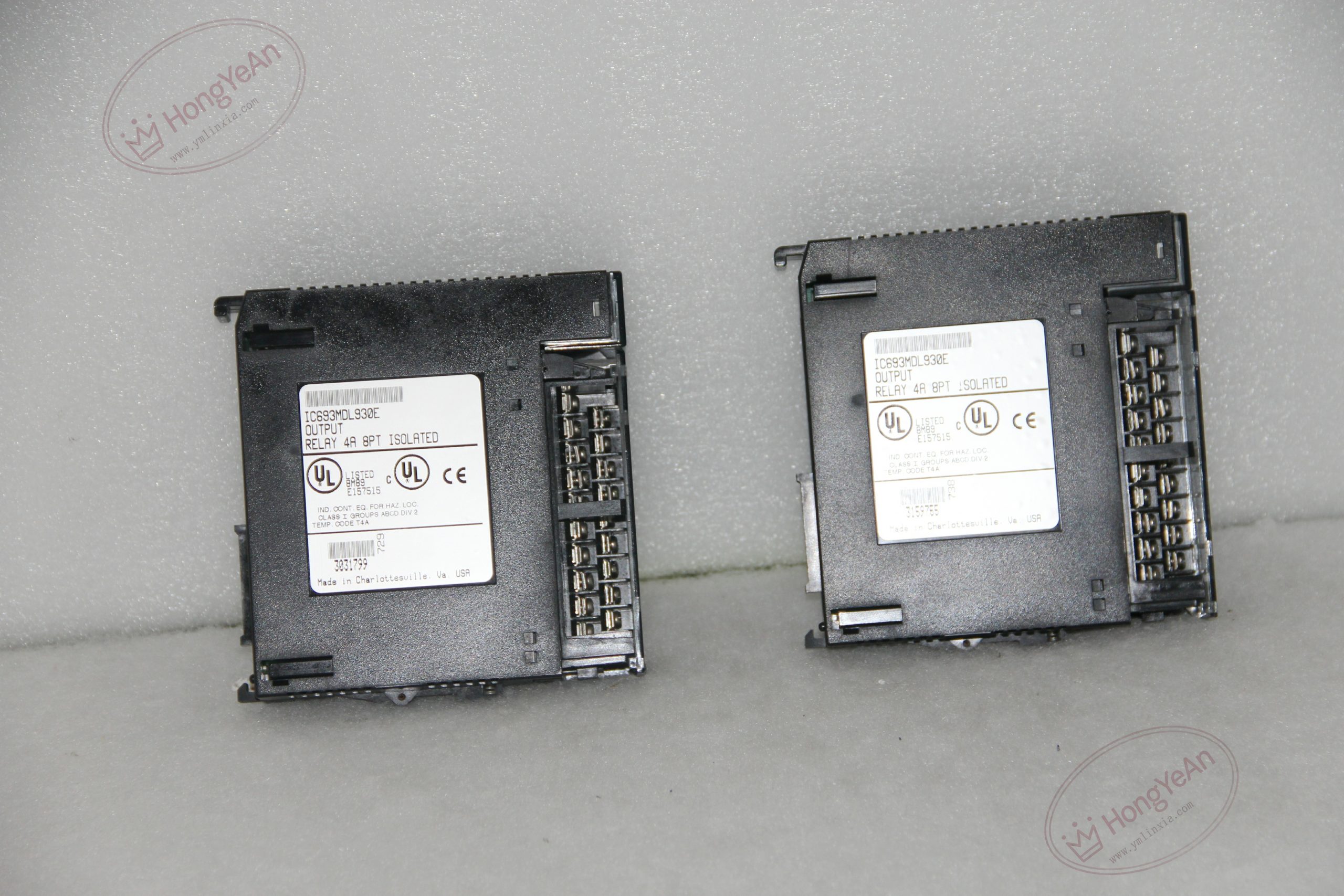
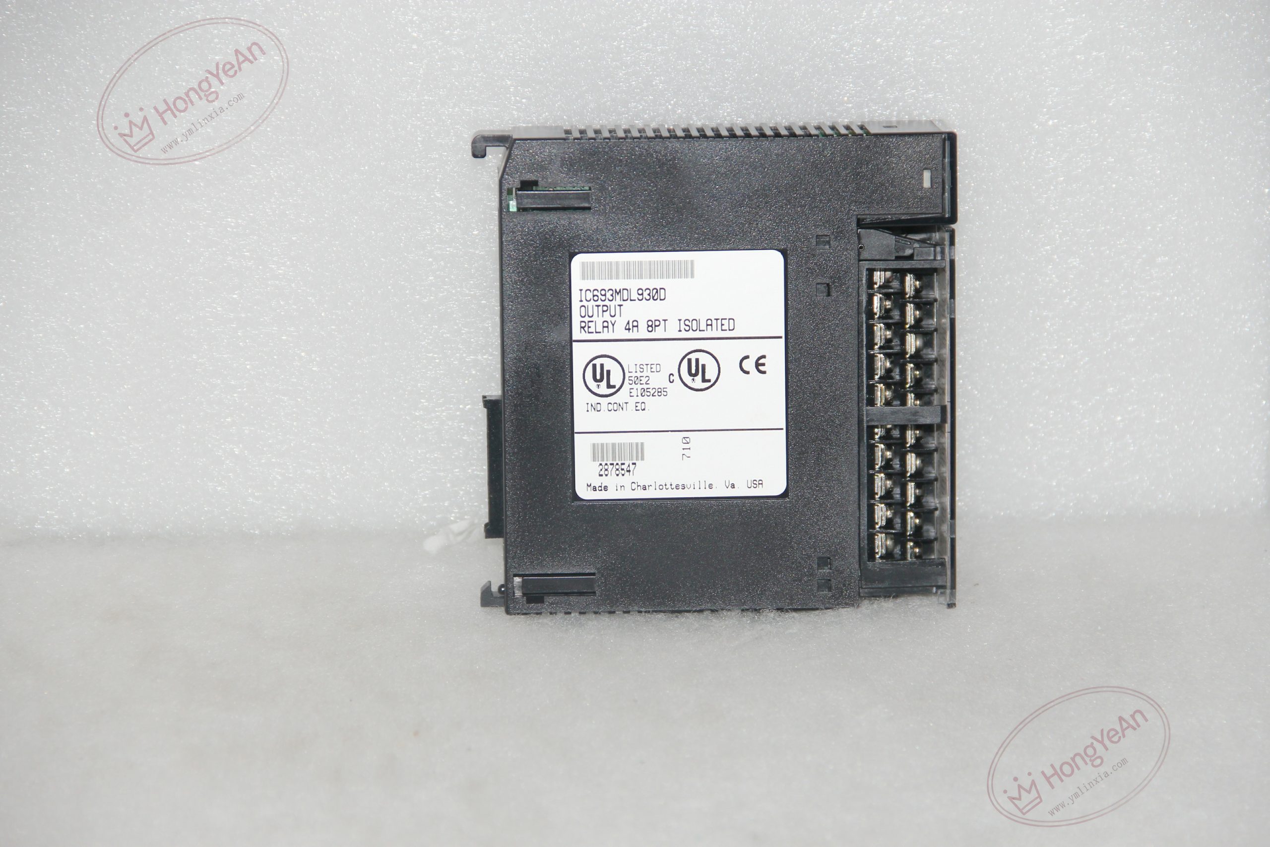
Description
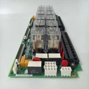
Key Technical Parameters ‑ Channel specification: 8 independent normally‑open relay contacts, each channel owns separate common terminal ‑ Load range: 5‑250VAC, 5‑30VDC; resistive load rating 4A per single point ‑ Switching performance: Max 10 ms turn‑on delay, max 5 ms turn‑off delay ‑ Isolation rating: 1500V RMS dielectric strength between individual channels as well as between field side and PLC backplane ‑ Backplane power supply: 5VDC power drawn from rack backplane ‑ Status feedback: Dedicated green LED for each output channel ‑ Mechanical lifecycle: Relay mechanical life ≥1 000 000 operations; electrical life varies with actual load type ‑ Environment requirement: 0‑60℃, cabinet‑mount installation, non‑condensing atmosphere ‑ Note: No built‑in fuses on module; external over‑current protection needs to be configured on field circuit
Practical Application Features Complete galvanic separation among every output channel allows mixing different‑voltage loads on one single module. Relay contact design supports cross‑voltage‑domain switching, removing the restriction of only DC‑side loads compared with transistor output boards. Channel‑by‑channel LED indication helps technicians quickly verify executing status during commissioning and routine maintenance. The module does not support hot‑swap; power‑off operation is mandatory when plugging or pulling out the unit from rack.
Field Installation & Commissioning Notes Insert the module into any available I/O slot of Series 90‑30 main or expansion rack and lock the latch tightly. Field‑side AC or DC power source shall be provided externally for loads; do not take power from PLC rack auxiliary circuit. Configure external fuse protection for each output loop to cope with short‑circuit risks, as there is no internal fuse inside the module. Surge‑suppression components are strongly recommended for inductive loads to absorb relay‑contact back‑EMF and extend contact service life. Keep high‑voltage relay‑output wiring physically separated from low‑signal input cables to avoid interference coupling. Complete hardware configuration inside programming tool before putting the whole system into running status.
Real‑World Troubleshooting Reference
- Module LED lights up but load fails to act: Check open‑circuit field wiring, failed load device, or loss of external field power supply.
- Single‑channel cannot switch any more: Mostly caused by relay‑contact burnout after excessive‑current impact or long‑time inductive‑load switching.
- Unstable intermittent action: Inspect loose terminal connection, aging relay contact, or occasional surge impact on field loop.
- Multiple‑point abnormal output: Surge voltage invades backplane circuit and causes internal driving‑circuit damage.
- No response to PLC logic commands: Check backplane contact condition, module hardware integrity and output‑address configuration in project.
-1-300x300.jpg)
Reviews
There are no reviews yet.