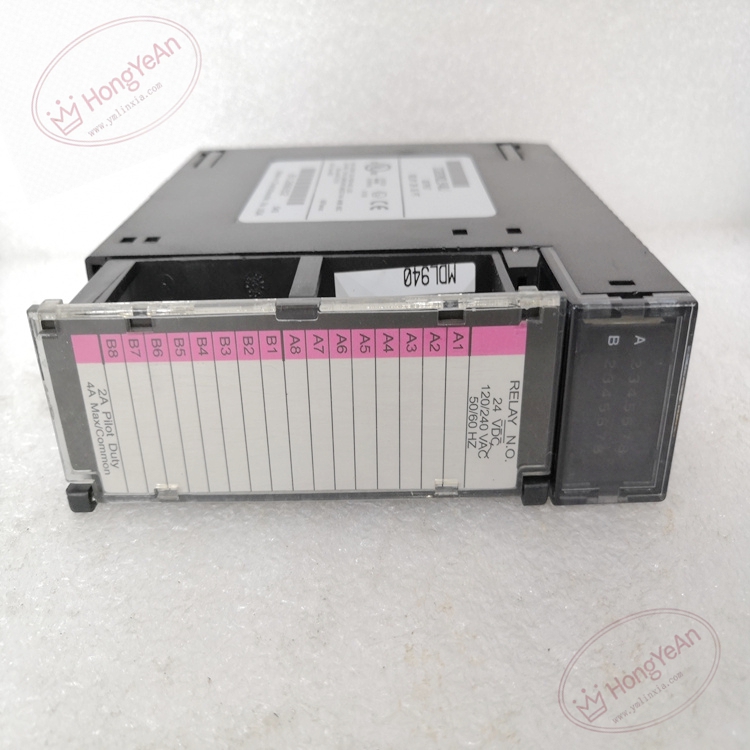
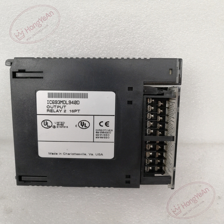
Description
Hardware & Electrical Specifications
‑ Model:IC693MDL940 ‑ Part Number:IC693MDL940 ‑ Module Type:Series‑90‑30 16‑Point Relay Output Module ‑ Mounting:Plug‑in onto any I/O slot of Series‑90‑30 backplane ‑ Backplane power consumption: • 5VDC bus:7 mA (all outputs ON) • 24VDC relay drive bus:135 mA (all outputs ON) ‑ Output channel:16‑point NO normally‑open relay output, 4 groups ×4 points ‑ Load voltage range: • DC:5‑30 VDC • AC:5‑250 VAC, 50/60Hz ‑ Load current: • Per‑channel resistive max:2 A • Per‑group common terminal max:4 A • Minimum load current:10 mA • Peak inrush current:5 A max ‑ Response time:ON max 15 ms; OFF max 15 ms ‑ Isolation: • Field‑to‑logic backplane:1500 VAC 1‑minute withstand • Between output groups:500 VAC isolation • No isolation between points inside same group ‑ Terminal:Removable screw‑type terminal block ‑ PCB treatment:Conformal coated for dust‑moisture‑corrosion resistance ‑ On‑board feature:No internal channel fuse; external fuse required for field loop protection ‑ Compatibility note:Cannot run standalone; install in Series‑90‑30 base rack; inductive loads need free‑wheel diode / RC absorption circuit; full discrete‑loop simulation test mandatory after replacement。
Environmental Specifications
‑ Operating temperature:0 ℃ ~ +60 ℃ ‑ Storage temperature:‑40 ℃ ~ +85 ℃ ‑ Relative humidity:5%‑95% non‑condensing ‑ Installation location:Indoor industrial control cabinet, IP20 ‑ EMC compliance:IEC 61000‑6‑2 ‑ Certifications:CE, UL Class I Div 2 hazardous‑location certification
Mechanical Data
‑ Weight:approx 0.40 kg ‑ Dimension:Series‑90‑30 standard single‑slot module form‑factor ‑ Handling note:ESD‑sensitive relay drive circuit, anti‑static wrist‑strap mandatory during handling; inductive loads must add absorption protection
Main Functions
- Control field‑side solenoid valves, contactors, indicator lamps, motor starter auxiliary coils and other AC/DC loads via relay contact outputs.
- Receive output data from Series‑90‑30 CPU through backplane bus, drive relay contacts to switch external field power circuit.
- LED status indication: ‑ Green PWR:Module internal power‑on indicator ‑ 16 individual channel green LEDs:Real‑time status of each output point ON/OFF
Installation & Wiring Requirements
- Cut off PLC rack power and field‑side external load power before replacement. Hot‑swap is forbidden. Strict anti‑static protection when handling module.
- Insert IC693MDL940 fully into PLC backplane slot and lock latch.
- Field wiring strictly follow GE Series‑90‑30 hardware manual; for inductive loads (coil, contactor), install RC‑snubber or free‑wheel diode absorption components; add external fuse for each group output; separate output cables from high‑power cables, connect shielding to protective ground terminal.
- Complete protective grounding according to GE system specification.
- After replacement:power‑on rack, verify PWR and channel LED status; perform full‑channel output trigger test.
- Replacement note: Calculate group current not to exceed 4A per‑common limit; inductive load absorption protection is mandatory; full system commissioning test mandatory before unit put‑into‑service.
-1-300x300.jpg)
Reviews
There are no reviews yet.