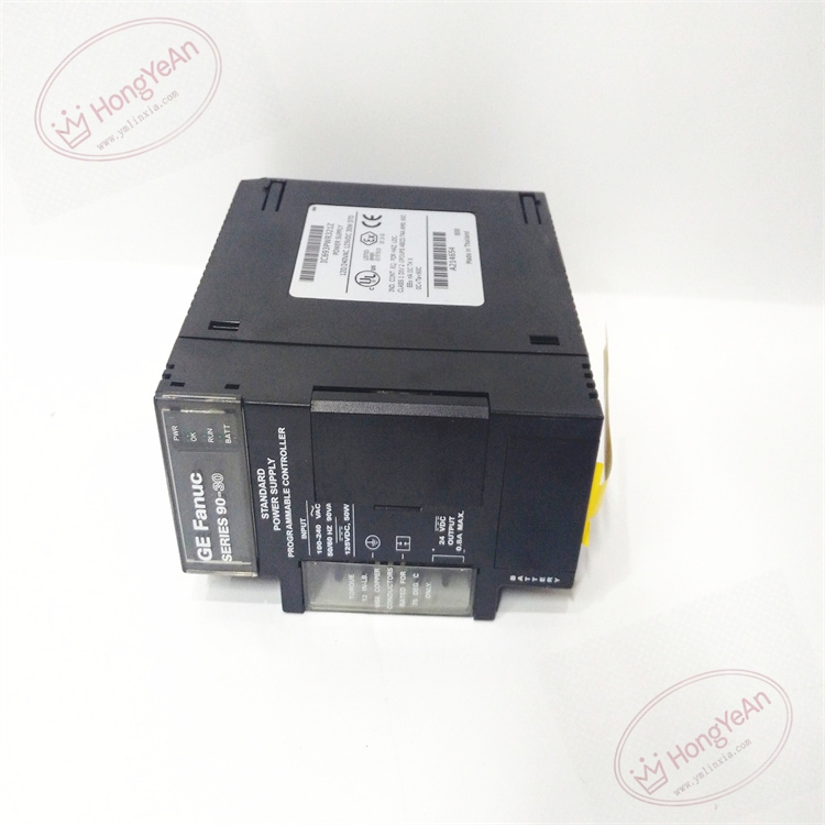
Description
Hardware & Electrical Specifications
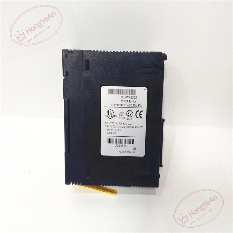
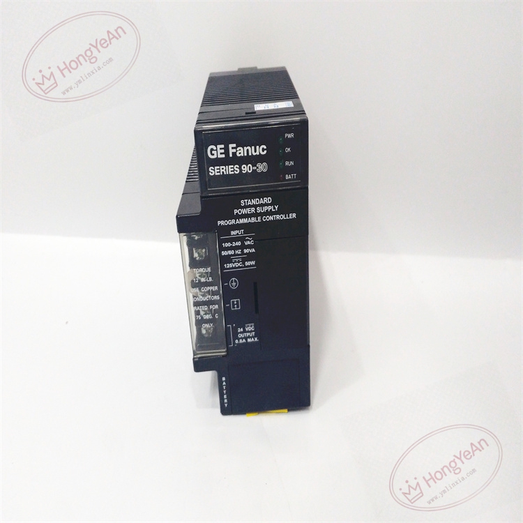
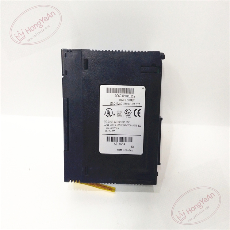
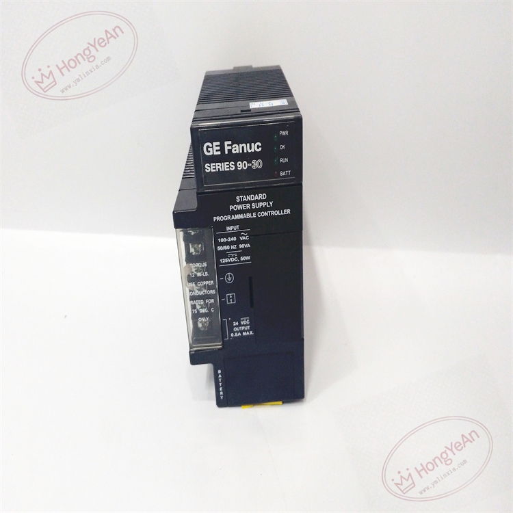
‑ Model:IC693PWR321 ‑ Part Number:IC693PWR321 ‑ Module Type:Series‑90‑30 Standard 30W Rack Power‑Supply Module ‑ Mounting:Far‑left dedicated power‑supply slot on Series‑90‑30 main baseplate only ‑ Input range: • AC:85‑264 VAC, 50/60Hz • DC:100‑300 VDC (nominal 125 VDC) ‑ Max input consumption:90VA(AC), 50W(DC) ‑ Peak inrush current:4A / 250ms ‑ Output rails (total 30W): • +5 VDC backplane logic:15 W, supply CPU & all back‑plane modules • +24 VDC Relay power:15 W, drive relay‑type output modules (MDL940 etc.) • Isolated +24 VDC auxiliary:20 W, isolated auxiliary power ‑ Serial port:RS‑485 SNP‑X port on front terminal, for programming, HMI, SNP‑X slave communication ‑ Built‑in protection:Over‑voltage, over‑current, short‑circuit protection; field‑replaceable internal fuse ‑ Memory backup:RTC clock & CPU RAM data backup battery built‑inside power‑supply unit ‑ PCB treatment:Conformal coated for dust‑moisture‑corrosion resistance ‑ Compatibility note:Cannot install in I/O slot or expansion racks; calculate total 5VDC consumption of all modules inside main rack must not exceed power budget; expansion racks need independent power supply; full rack power‑load check mandatory after replacement。
Environmental Specifications
‑ Operating temperature:0 ℃ ~ +60 ℃ ‑ Storage temperature:‑40 ℃ ~ +85 ℃ ‑ Relative humidity:5%‑95% non‑condensing ‑ Installation location:Indoor industrial control cabinet, IP20 ‑ EMC compliance:IEC 61000‑6‑2 ‑ Certifications:CE, UL Class I Div 2 hazardous‑location certification
Mechanical Data
‑ Weight:approx 0.35 kg ‑ Dimension:Series‑90‑30 standard single‑slot power‑supply form‑factor ‑ Handling note:ESD‑sensitive power circuit; pay attention to internal backup‑battery aging during maintenance; replace fuse only with GE‑specified part number ‑ Terminal tightening torque:0.6‑1.0 N·m
Main Functions
- Main rack power source, convert AC/DC field input into 5VDC logic bus, 24V relay‑drive and isolated 24V auxiliary power for main‑base CPU and I/O modules.
- Integrated RS‑485 SNP‑X serial port, serves as programming/download and HMI communication channel for CPUs without onboard serial port.
- Built‑in battery maintains real‑time clock and CPU RAM data during power‑off condition.
- Hardware protective function for over‑voltage, over‑current and short‑circuit fault.
- LED status indication on front panel: ‑ Green OK:Power‑supply normal output indicator ‑ FAULT:Over‑voltage / over‑current / fuse failure alarm
Installation & Wiring Requirements
- Cut off PLC main input power before replacement. Hot‑swap is forbidden. Strict anti‑static protection when handling power‑supply module.
- Insert IC693PWR321 into far‑left dedicated power‑supply slot of main baseplate and lock latch.
- Main‑source power wiring strictly follow GE hardware manual; use suitable‑rating wire and external circuit breaker; separate power input cable from signal cables, connect protective ground reliably.
- RS‑485 SNP‑X serial wiring: use shielded twisted‑pair, install terminating resistor at bus tail end.
- After replacement:power‑on main input, verify OK / FAULT LED status; measure three DC output rail voltage; verify SNP‑X serial communication; calculate total 5VDC load consumption of all plug‑in modules.
- Replacement note: Confirm main‑rack total power consumption within 30W rating; expansion racks cannot draw power from this power‑supply; inspect internal backup‑battery health; full‑system power‑on commissioning test mandatory before unit put‑into‑service。
Reviews
There are no reviews yet.