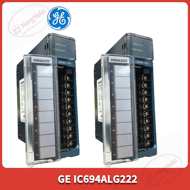
Description
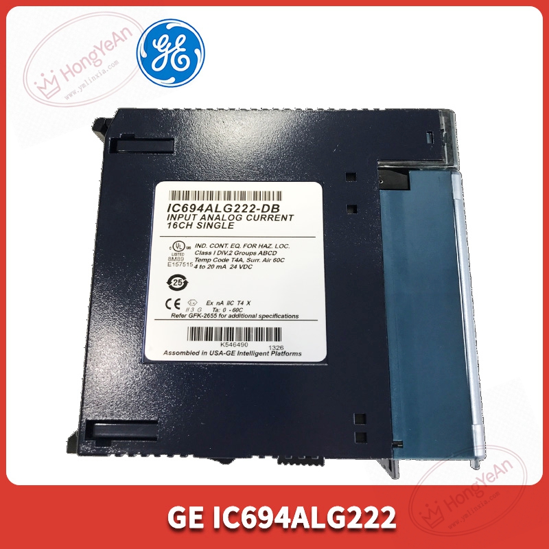
Core performance features
‑ Channel configuration: 16 single‑ended voltage inputs or 8 differential voltage inputs, software‑selectable working mode, no hardware jumper modification required. ‑ Supported input ranges: ‑10 V ~ +10 V bipolar range, 0 ~ +10 V unipolar range. ‑ Resolution: 12‑bit A/D conversion; accuracy ±0.25 % full‑scale at 25 °C ambient temperature. ‑ Module scan speed: 6 ms for full 16‑channel single‑ended scan; 3 ms for 8‑channel differential scan. Built‑in configurable digital filter for restraining field signal jitter. ‑ Isolation level: 1500 V AC isolation between back‑plane logic side and field input side, improving anti‑interference performance in industrial cabinet environment. ‑ Power requirement: 5 VDC obtained from RX3i back‑plane; when installed in universal back‑plane slot, external isolated 24 VDC power must be supplied via TB1 terminal; expansion back‑plane acquires auxiliary power from rack power module directly. ‑ Diagnosis function: on‑board hardware monitors module health status, channel over‑range fault; high‑alarm / low‑alarm threshold can be set for each channel; fault status bits can be uploaded to controller logic. ‑ Mechanical property: occupies one single slot on RX3i back‑plane; supports hot‑swap under system running condition. ‑ Environmental index: operating temperature ‑20 ~ +60 ℃; storage temperature‑40 ~ +85 ℃; humidity 5‑95 % non‑condensing; IP20 protection grade, only for cabinet‑internal installation. ‑ Supporting software: Proficy Machine Edition for module hardware configuration, alarm‑limit setting and channel parameter downloading.
Physical appearance
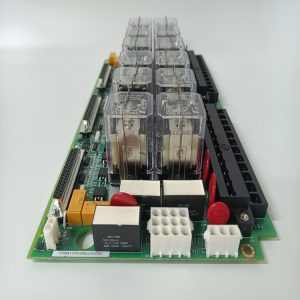
Standard RX3i series plug‑in module, metal‑plastic composite housing, horizontal insert into RX3i rack back‑plane slot. ‑ Front panel: several LED indicator lamps for Module OK, channel fault status; model label printed IC694ALG222. ‑ Front‑mounted detachable 20‑pin screw terminal block, all field voltage signal wiring connects to this terminal assembly. ‑ Rear side: gold‑finger contacts for back‑plane power supply and internal bus data exchange. ‑ It is a back‑plane plug‑in module, not DIN‑rail mounting device.
On‑site application scenarios
Installed inside factory, petrochemical and power‑plant control cabinets. It collects analog voltage signals from transmitters, displacement sensors and potentiometer devices, and transmits measured values to RX3i CPU for regulation, interlock and data‑recording. When this module fails, corresponding analog measuring points will turn invalid, but will not crash the whole PLC system. After spare‑part replacement, download original hardware configuration, verify single‑ended / differential mode setting, check each channel reading value and alarm‑limit function before putting online.
Installation & operating notes
‑ Hot‑swap function is supported in theory, but power‑off replacement is recommended in high‑vibration industrial site to avoid scratch damage to gold‑finger contacts. ‑ Field analog signal cables must adopt shielded wire, keep physical separation from high‑power power cables to reduce electromagnetic interference causing reading jitter. ‑ Confirm power supply mode according to back‑plane type (universal or expansion back‑plane), missing external 24 VDC auxiliary power will lead to module abnormal operation. ‑ Do not open module housing on‑site. Component‑level repair will invalidate industrial certification; replace whole module for permanent hardware damage.
Common field phenomena & troubleshooting
- Module OK indicator off: Check rack back‑plane 5 VDC power supply; if universal back‑plane is used, verify external isolated 24 VDC input condition; re‑seat module firmly in slot.
- Analog reading value zero or full‑scale overflow: Inspect field transmitter wiring, check software channel mode setting (single‑ended / differential mismatch is frequent fault point).
- Measured value continuous jitter: Optimize digital‑filter parameter in configuration software; inspect cable shielding grounding status, eliminate surrounding strong interference sources.
- Partial channel high‑low alarm triggered: Check actual field signal value, distinguish real process‑field fault from module hardware abnormal.
- Cannot download configuration: Verify firmware version compatibility between module and RX3i CPU; check back‑plane bus communication status.
-300x300.jpg)
Reviews
There are no reviews yet.