Description
Hardware & Electrical Specifications
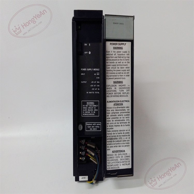
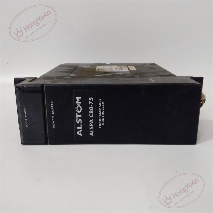
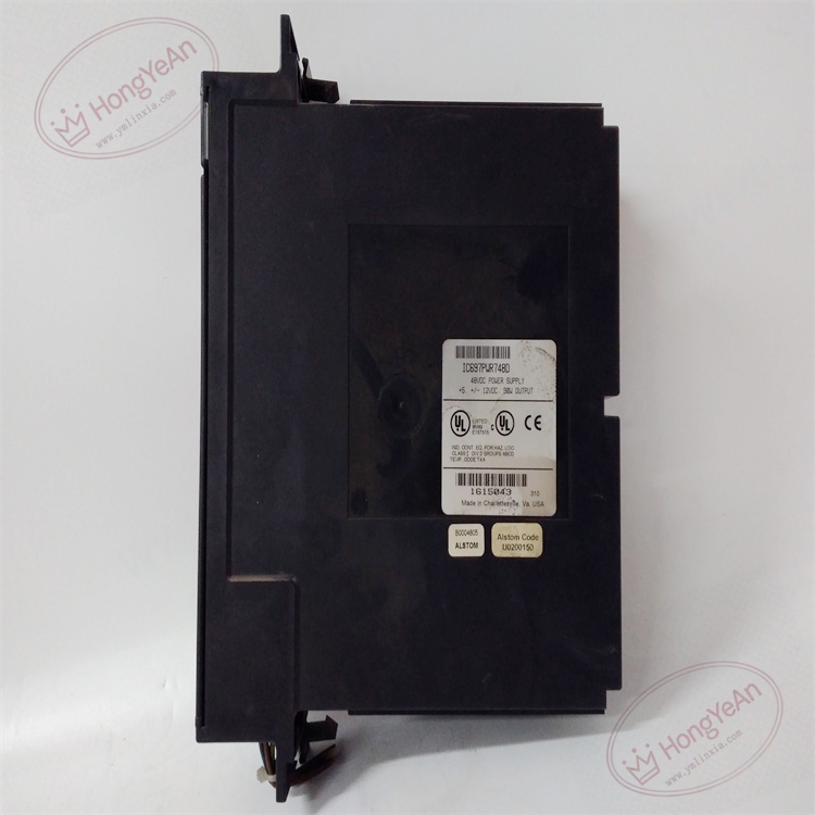
‑ Model: IC697PWR748D ‑ Part Number: IC697PWR748D ‑ Module Type: Series 90‑70 Rack Power Supply Module, occupies left‑most slot of Series 90‑70 backplane ‑ Mounting: Series 90‑70 main chassis only; must be installed in the far‑left slot position ‑ Input specifications: • Nominal input voltage: 48 VDC • Input operating range: 35 VDC ~ 60 VDC • Maximum input power: 160 W at full‑load • Inrush energy: Max 28 J @ 60 VDC ‑ Output specifications (total combined 90 W max): • +5 VDC: 18 A maximum, minimum load 1 A • +12 VDC: 1.5 A maximum • −12 VDC: 1 A maximum • Ripple noise: < 60 mV peak‑to‑peak ‑ Power ride‑through: Minimum 10 ms hold‑up time under full‑load condition ‑ Dual‑rack capability: Can supply second rack via IC697CBL700 extension cable ‑ Protection features: Electronic over‑current, short‑circuit protection on +5 V bus; electronic over‑voltage clamping; internal 5 A 250 V 5×20 mm field‑replaceable fuse ‑ Diagnostics: Front‑panel power OK and fault status indicators; power‑fail logic sequencing signals to backplane for CPU power‑loss detection ‑ PCB treatment: Conformal coated for dust, moisture and corrosion resistance ‑ Compatibility note: Revision‑D drop‑in replacement for earlier IC697PWR748 hardware revisions. Total rack load must be calculated and kept below 90 W aggregate output rating. Hot‑swap prohibited. After replacement, verify input DC voltage, check backplane output voltages and confirm stable operation of all rack modules.
Environmental Specifications
‑ Operating temperature: 0 ℃ ~ +50 ℃; derate output 3 % per ℃ above +45 ℃ ‑ Storage temperature: −40 ℃ ~ +85 ℃ ‑ Relative humidity: 5%‑95% non‑condensing ‑ Installation location: Indoor control cabinet, IP20 protection class ‑ EMC compliance: IEC 61000‑6‑2 ‑ Certifications: CE, UL Class I Div 2 hazardous‑location certification
Mechanical Data
‑ Weight: approx 1.6 kg ‑ Dimension: Series 90‑70 standard single‑slot module form‑factor
Main Functions
- Converts 48 VDC field input into tightly‑regulated +5 V / +12 V / −12 V backplane power for all Series 90‑70 modules within the rack. Generates power‑fail sequencing signals so the CPU can execute orderly power‑down housekeeping tasks before DC bus collapse.
- Optional dual‑rack power feeding reduces quantity of power supplies in multi‑rack system when total load permits.
- Built‑in electronic protection prevents backplane damage caused by field short‑circuit or overload events.
- Front‑panel LED indicators: ‑ Green PWR OK: Power supply outputs within normal operating range ‑ Red FAULT: Over‑voltage, over‑current, short‑circuit or input power failure condition
Installation & Wiring Requirements
- Cut off 48 VDC field input power before installation or replacement. Hot‑swap is not permitted. Apply ESD protection during module handling.
- Insert IC697PWR748D into the far‑left dedicated power‑supply slot of Series 90‑70 chassis and fasten module latch. If dual‑rack power feeding is required, connect IC697CBL700 cable between this unit and second rack.
- Field 48 VDC input wiring comply with manual GFK‑1061D. Use appropriate wire gauge matched to input current; install external over‑current protection upstream of power‑supply terminals. Reliable protective‑ground connection for rack chassis is mandatory.
- After replacement: Restore 48 VDC input power, observe front‑panel LED status. Measure backplane +5 V, ±12 V output voltages. Verify all CPU, communication and I/O modules boot and operate normally. For dual‑rack configuration, confirm load calculation is within 90 W total output limit.
- Replacement note: Always calculate total rack power consumption before adding new modules to avoid overloading power‑supply unit. Full‑system commissioning test is mandatory before putting into service.
-1-1-300x300.jpg)
Reviews
There are no reviews yet.