Description
Hardware & Electrical Specifications
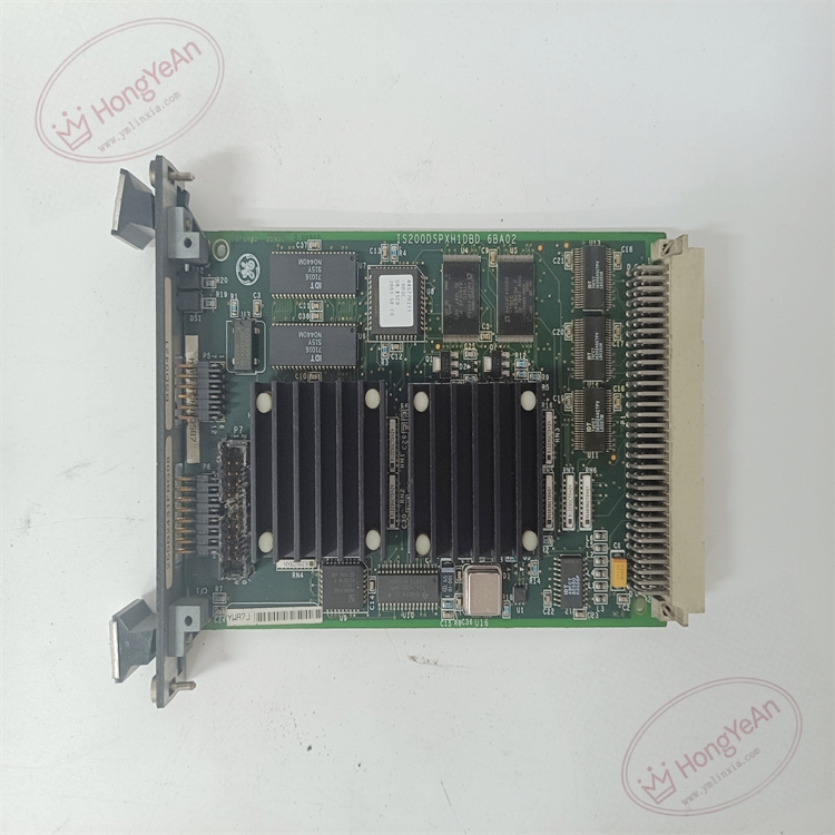
- Model:IS200DSPXH1DBD
- Part Number:IS200DSPXH1DBD
- Module Type:DSPX Digital‑Signal‑Processor Control Board
- Form factor:Single‑slot 3U VME rack module
- Power supply:+5 V DC supplied by rack backplane, typical power consumption 10 W
- Core chip:60 MHz DSP + custom ASIC, on‑board FLASH / RAM / NVRAM memory
- Backplane interface:VME bus, dual‑channel ISBus communication interface
- Front‑panel connectors:multiple dedicated signal connectors for excitation gating and interlock signals
- PCB treatment:Conformal coated for dust‑moisture‑corrosion resistance
- On‑board protection:ESD protection, surge suppression, hardware watchdog circuit
- Compatibility note:Cannot run standalone; for GE Mark VI / EX2100 excitation system; must match firmware revision and system configuration; pin‑to‑pin compatible with IS200DSPXH1DBC, but parameters and firmware must be verified after replacement, cannot directly swap without test.
Environmental Specifications
- Operating temperature:‑40 ℃ ~ +85 ℃
- Storage temperature:‑40 ℃ ~ +85 ℃
- Relative humidity:5%‑95% non‑condensing
- Installation location:Inside turbine / excitation control cabinet VME rack
- EMC compliance:IEC 61000‑6‑2
- Certifications:CE
Mechanical Data
- Weight:approx 1.0 kg
- Dimension:216 mm × 162 mm × 40 mm
- Connector:VME P1/P2 backplane edge connector, front‑panel dedicated signal connectors
- Handling note:ESD‑sensitive PCB, anti‑static wrist strap mandatory during handling
- Recommended wire cross‑section:0.75 mm²‑2.5 mm² copper cable for signal terminals
- Terminal tightening torque:0.6‑1.0 N·m
Main Functions
- Execute high‑speed real‑time excitation closed‑loop control algorithm for EX2100 generator excitation system.
- Generate precise SCR thyristor firing gating pulses for excitation power bridge.
- Collect generator field voltage & field‑current measurement data, perform PID regulation calculation.
- Implement field‑flashing logic, excitation start‑stop sequence and hardware trip interlock protection logic.
- Store critical parameters and fault event data in on‑board NVRAM memory.
- High‑speed data interaction with main CPU and other functional boards via VME / ISBus backplane bus.
- On‑board self‑diagnosis: detect DSP operation fault, memory error, bus communication failure, report fault status to controller.
- Front‑panel LED status indication:
- Green LED:Power supply normal, module healthy
- Yellow LED:ISBus / VME bus communication active
- Red LED:Hardware fault / algorithm trip / communication loss
Installation & Wiring Requirements
- Cut off rack power supply before replacement. Hot‑swap is forbidden. Strict anti‑static protection when handling PCB board.
- Insert module fully into VME rack slot, lock ejector levers to guarantee reliable backplane connection.
- Connect front‑panel excitation‑related signal cables strictly follow GE EX2100 wiring drawing; separate weak‑signal cables from high‑power cables.
- Complete protective grounding according to GE Speedtronic system specification.
- After replacement: verify firmware version consistency, download excitation control parameters, complete bus communication test, perform static firing test before commissioning.
- Replacement note: Firmware version matching is mandatory. Although pin‑to‑pin compatible with IS200DSPXH1DBC, full‑function excitation‑loop test must be carried out after replacement.
-1-300x300.jpg)
Reviews
There are no reviews yet.