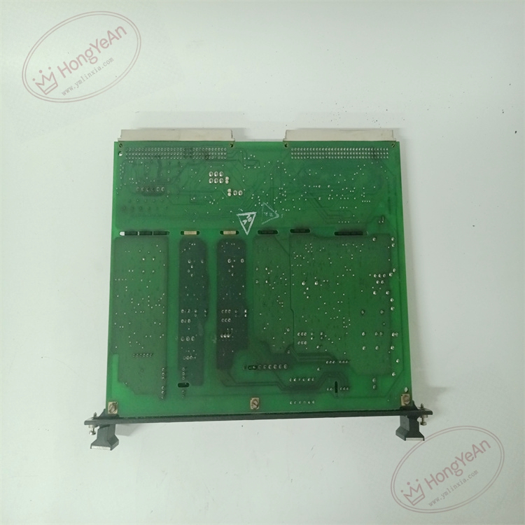
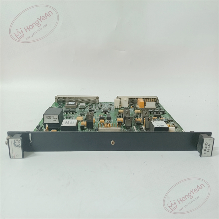
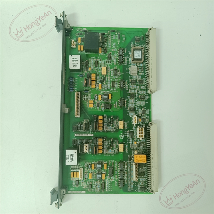
Description
Hardware & Electrical Specifications
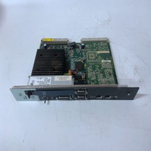
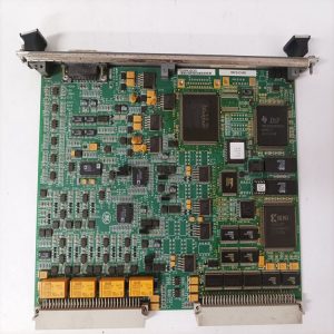
- Model:IS200ERDDH1ABA
- Part Number:IS200ERDDH1ABA
- Module Type:ERDD IGBT Exciter Regulator Dynamic‑Discharge Board
- Form factor:Single‑slot double‑height 6U VME‑compatible plug‑in board
- Power supply:+5 V / 24 V DC supplied by ERBP / ERRB exciter backplane
- Drive function:IGBT gate drive control for excitation power converter
- Monitoring:DC‑link voltage sensing, field voltage‑current feedback sampling; on‑board RTD channel for power bridge temperature measurement (0‑140 ℃)
- Discharge function:Dynamic discharge circuit for DC‑link over‑voltage suppression
- Relay control:Drive K3 charging relay (simplex mode); drive K41 de‑excitation relay (redundant mode)
- Backplane interface:Dual 96‑pin P1/P2 backplane connectors; multiple front‑panel dedicated signal connectors
- PCB treatment:Conformal coated for dust‑moisture‑corrosion resistance
- On‑board protection:Over‑voltage surge suppression, short‑circuit hardware interlock, ESD protection
- Compatibility note:Cannot run standalone; dedicated for GE EX2100 excitation system; installation slot must match simplex/redundant architecture; full function test required after replacement。
Environmental Specifications
- Operating temperature:‑40 ℃ ~ +70 ℃
- Storage temperature:‑40 ℃ ~ +85 ℃
- Relative humidity:5%‑95% non‑condensing
- Installation location:Excitation cabinet ERBP / ERRB rack
- EMC compliance:IEC 61000‑6‑2
- Certifications:CE
Mechanical Data
- Weight:approx 1.0 kg
- Dimension:340 mm × 216 mm × 55 mm
- Handling note:ESD‑sensitive PCB, anti‑static wrist‑strap mandatory during handling
- Recommended wire cross‑section:0.75‑2.5 mm² shielded twisted‑pair copper cable for power‑unit signal wiring
- Terminal tightening torque:0.6‑1.0 N·m
Main Functions
- Output gate‑drive trigger signals to IGBT power devices of EX2100 excitation power bridge.
- Dynamic discharge circuit suppresses DC‑link over‑voltage to protect power semiconductor components during system trip and transient disturbance.
- Collect field voltage, field current and power‑unit temperature feedback signals, transmit measured data to DSPX controller via backplane bus.
- Control K3 charging relay under simplex configuration; control K41 de‑excitation relay for redundant dual‑regulator coordination.
- Hardware fault detection for IGBT drive circuit, discharge loop and temperature‑sampling channel; report fault alarm to main controller.
- On‑board self‑diagnosis: detect power failure, backplane communication abnormality, circuit fault.
- Front‑panel LED status indication:
- Green LED:Board power supply normal
- Yellow LED:Back‑plane data communication active
- Red LED:Drive‑circuit fault / over‑voltage / hardware failure
Installation & Wiring Requirements
- Cut off excitation rack power supply before replacement. Hot‑swap is forbidden. Strict anti‑static protection when handling PCB board.
- Insert module fully into ERBP or ERRB designated slot according to system simplex/redundant configuration, ensure reliable back‑plane connector contact.
- Connect IGBT drive, feedback‑signal cables strictly follow GE EX2100 wiring manual; separate power‑signal cables from weak‑signal control cables.
- Complete protective grounding according to GE Speedtronic system specification.
- After replacement: verify back‑plane communication status, perform static IGBT trigger test, simulate DC‑link over‑voltage discharge test before commissioning.
- Replacement note: Confirm rack slot matches system redundancy mode; full‑loop excitation function test is mandatory after swap。
Reviews
There are no reviews yet.