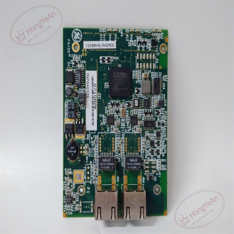
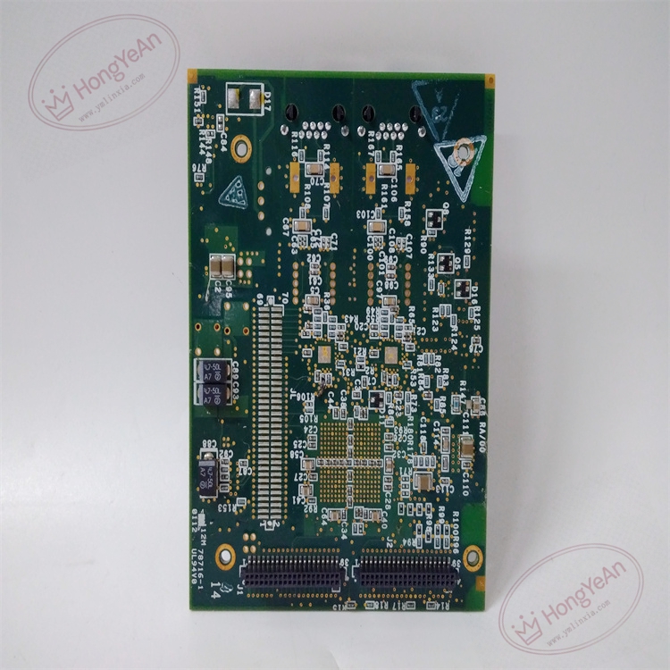
Description
Hardware & Electrical Specifications
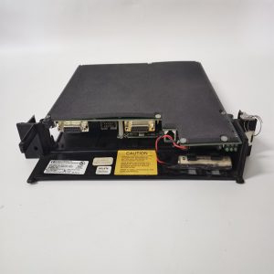
- Model:IS200HSLAH2ADE
- Part Number:IS200HSLAH2ADE
- Module Type:High‑Speed Logic‑Analog Terminal Board (HSLA)
- Mounting:DIN‑rail bracket installation inside turbine control cabinet
- Power supply:+24 V DC / ±15 V DC supplied by system rack backplane
- Speed input:2‑channel magnetic pickup(MPU) / active speed sensor input, max input frequency 20 kHz, jumper‑configurable threshold level
- Analog channel:Multi‑channel high‑speed analog input/output for valve position feedback and control output
- Discrete I/O:Fast digital interlock input & relay‑type output for turbine protection logic
- Communication:HSSL high‑speed serial link interface, connect to corresponding I/O pack via dedicated ribbon cable
- Galvanic isolation:Channel‑to‑channel and field‑to‑logic isolation for anti‑interference in heavy‑industrial environment
- PCB treatment:Conformal coated for dust‑moisture‑corrosion resistance
- On‑board protection:ESD protection, surge suppression, input over‑voltage clamp circuit
- Compatibility note:Cannot run standalone; must match corresponding HSLA I/O core pack; jumper configuration must restore after replacement; full‑loop speed & valve‑control function test required for TMR system。
Environmental Specifications
- Operating temperature:‑30 ℃ ~ +65 ℃
- Storage temperature:‑40 ℃ ~ +85 ℃
- Relative humidity:5%‑95% non‑condensing
- Installation location:Indoor turbine control cabinet
- EMC compliance:IEC 61000‑6‑2
- Certifications:CE
Mechanical Data
- Weight:approx 1.30 kg
- Dimension:210 mm × 160 mm × 60 mm
- Connector:Multi‑group D‑Sub and screw terminal blocks; dedicated HSSL ribbon‑cable connector for I/O pack
- Handling note:ESD‑sensitive PCB, anti‑static wrist‑strap mandatory during handling
- Recommended wire cross‑section:0.75‑2.5 mm² shielded twisted‑pair copper cable for field‑sensor wiring
- Terminal tightening torque:0.6‑1.0 N·m
Main Functions
- Terminate magnetic pickup pulse signals from turbine shaft for rotating‑speed measurement and overspeed protection logic.
- Condition high‑speed analog feedback signals from valve LVDT position sensors.
- Receive fast discrete interlock‑trip signals and output discrete control commands for turbine protection logic.
- Signal filtering and surge suppression for long‑distance field wiring in high‑EMI power‑plant environment.
- Transmit conditioned field signals to matched I/O pack via HSSL high‑speed serial link, achieve low‑deterministic‑latency data transmission for governor loop.
- On‑board channel self‑diagnosis: detect MPU open‑circuit, signal over‑range, loop fault, report fault status to main controller.
- LED status indication:
- Green LED:Terminal‑board auxiliary power normal
- Yellow LED:HSSL link communication active
- Red LED:Field‑channel fault / link communication loss
Installation & Wiring Requirements
- Cut off rack power supply before replacement. Hot‑swap is forbidden. Strict anti‑static protection when handling PCB board.
- Secure DIN‑rail mounting bracket firmly; ensure HSSL ribbon‑cable connector fully locked without loose contact.
- Restore on‑board jumper setting (MPU threshold, signal mode) strictly consistent with original configuration before field wiring.
- Field‑sensor wiring adopts shielded twisted‑pair; separate speed‑signal cables from high‑power cables to reduce electromagnetic interference; connect shielding to dedicated ground terminal.
- Complete protective grounding according to GE Speedtronic system specification.
- After replacement: verify HSSL link status, test turbine‑speed measuring value, validate valve‑position feedback and protection‑signal response before commissioning.
- Replacement note: Jumper configuration must be reproduced exactly; TMR redundant system requires three‑set channel consistency verification, full‑function test mandatory after swap.
-1-300x300.jpg)
Reviews
There are no reviews yet.