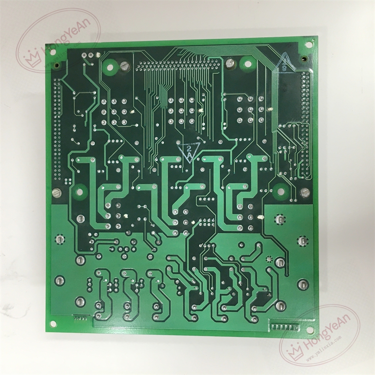

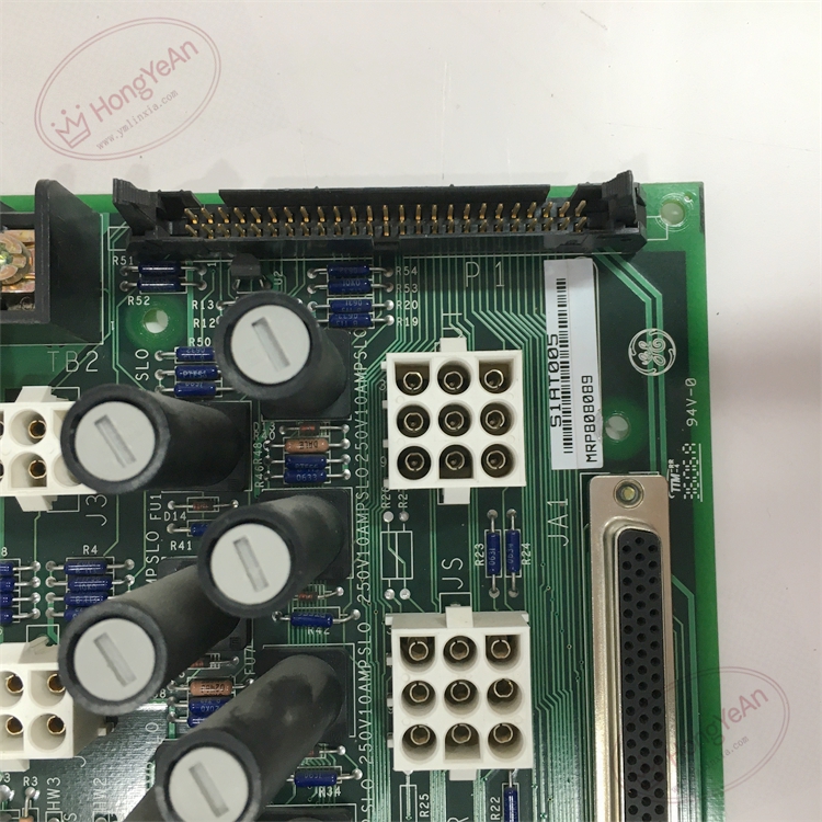
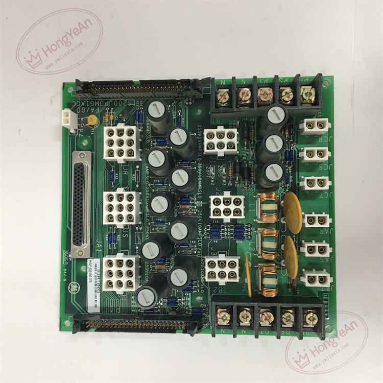
Description
Hardware & Electrical Specifications
- Model:IS200JPDMG1ACC
- Part Number:IS200JPDMG1ACC
- Module Type:JPDM Jumper‑Power‑Distribution Module
- Form factor:Single‑slot plug‑in board for Mark VI I/O rack
- Power input:Redundant 28 V DC system power input, max total current 25 A
- Output bus:Three independent R / S / T I/O power bus branches, each branch with individual fuse protection
- On‑board resource:Multiple jumper groups for bus‑mode configuration; fuse status feedback circuit for PPDA diagnostic interface
- Backplane interface:Multi‑pin edge connector for rack back‑plane power and status‑signal interconnection
- PCB treatment:Conformal coated for dust‑moisture‑corrosion resistance
- On‑board protection:Branch fuse over‑current protection, ESD protection, LC filter circuit for power‑rail noise suppression
- Compatibility note:Cannot run standalone; must match Mark VI I/O rack architecture and PPDA power‑diagnosis module; jumper setting must be restored exactly after replacement; fuse rating must conform to original design to avoid equipment damage。
Environmental Specifications
- Operating temperature:‑40 ℃ ~ +70 ℃
- Storage temperature:‑40 ℃ ~ +85 ℃
- Relative humidity:5%‑95% non‑condensing
- Installation location:Inside turbine control cabinet I/O rack
- EMC compliance:IEC 61000‑6‑2
- Certifications:CE, Class1 Div2 hazardous‑area compliance
Mechanical Data
- Weight:approx 1.05 kg
- Dimension:225 mm × 215 mm × 30 mm
- Handling note:ESD‑sensitive PCB, anti‑static wrist‑strap mandatory during handling
- Recommended wire cross‑section:1.5‑2.5 mm² copper cable for main power‑input wiring
- Terminal tightening torque:0.6‑1.0 N·m
Main Functions
- Accept redundant 28 V DC power supply from system power source for turbine I/O rack.
- Distribute power to R/S/T three independent I/O power buses for each I/O pack and field terminal boards.
- Independent fuse protection for each output branch, isolates short‑circuit fault and prevents fault propagation across rack.
- On‑board jumpers configure bus operating mode for simplex or TMR triple‑redundant system architecture.
- Collect fuse‑blow and power‑rail status, send diagnostic signal to PPDA module for system fault alarm.
- Hardware self‑diagnosis: detect input power loss, branch fuse failure, report fault status to turbine controller.
- Front‑panel LED status indication:
- Green LED:Board main power‑supply normal
- Yellow LED:Power‑bus output active
- Red LED:Branch fuse blown / input‑power abnormal fault
Installation & Wiring Requirements
- Cut off rack power supply before replacement. Hot‑swap is forbidden. Strict anti‑static protection when handling PCB board.
- Insert module fully into designated rack slot, ensure reliable locking of back‑plane edge connector.
- Restore on‑board jumper configuration and each branch fuse rating strictly consistent with original settings before power‑on.
- Main power‑input wiring strictly follow GE Mark VI wiring manual; separate power cables from weak‑signal analog cables.
- Complete protective grounding according to GE Speedtronic system specification.
- After replacement: verify each R/S/T bus output voltage, check PPDA power‑diagnosis alarm status, perform full‑I/O‑rack power‑on test before commissioning.
- Replacement note: Jumper positions and fuse rating cannot be arbitrarily modified; wrong setting will cause I/O module power‑supply failure or hardware burnout.
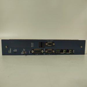
-300x300.jpg)
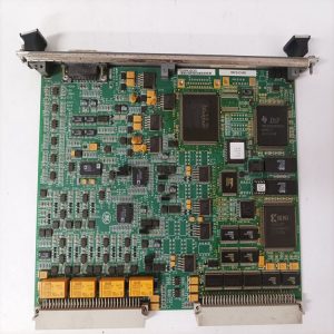
Reviews
There are no reviews yet.