Description
Hardware & Electrical Specifications
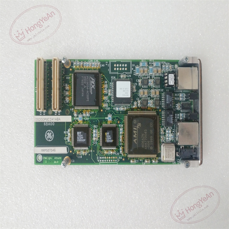
- Model:IS200PMCIH1ABA
- Part Number:IS200PMCIH1ABA
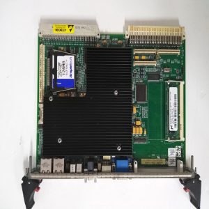
- Module Type:PMCI Processor‑Module Communication Interface Mezzanine Card
- Form factor:Compact mezzanine daughter‑board, plug‑in onto main CPU board
- Power supply:+5 V DC supplied by host processor board, typical power consumption 6 W
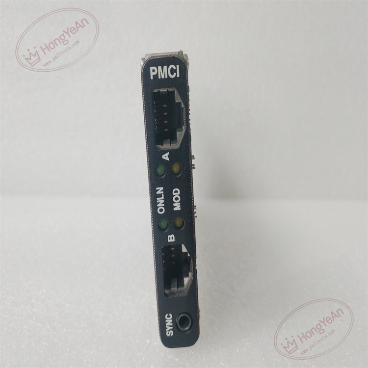
- Communication:Dual‑port 100BASE‑TX IONet Ethernet (Port A / Port B), SYNC time‑synchronization input interface
- Front‑panel indicator:PMCI panel with ONLN, MOD status LED, dual RJ45 Ethernet connectors, SYNC BNC sync‑signal jack
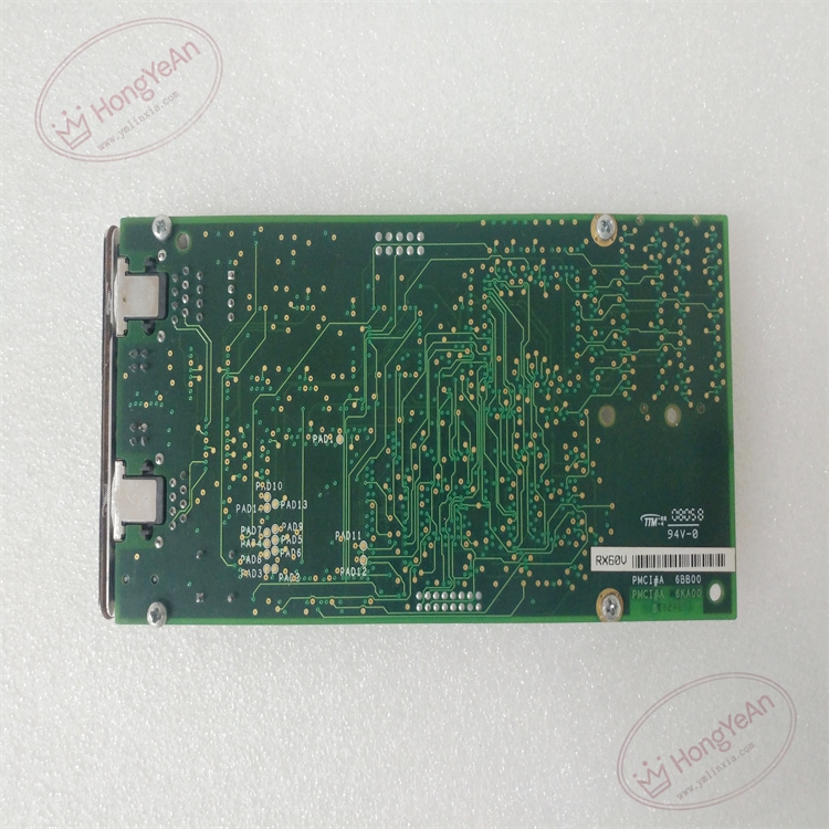
- PCB treatment:Conformal coated for dust‑moisture‑corrosion resistance
- On‑board protection:ESD protection, surge suppression, hardware watchdog circuit for link monitoring
- Compatibility note:Cannot run standalone; must mate with corresponding Mark VIe CPU main board; firmware revision must match system configuration; dual‑IONet link test required after replacement。
Environmental Specifications
- Operating temperature:‑40 ℃ ~ +70 ℃
- Storage temperature:‑40 ℃ ~ +85 ℃
- Relative humidity:5%‑95% non‑condensing
- Installation location:Turbine control cabinet CPU rack
- EMC compliance:IEC 61000‑6‑2
- Certifications:CE
Mechanical Data
- Weight:approx 0.28 kg
- Dimension:152 mm × 89 mm × 22 mm
- Connector:High‑density mezzanine gold‑finger connector for mating with CPU board; front‑panel RJ45 and SYNC BNC connector
- Handling note:ESD‑sensitive PCB, anti‑static wrist‑strap mandatory during handling
- Recommended wire cross‑section:Shielded CAT5e twisted‑pair copper cable for IONet network wiring
Main Functions
- Dual redundant IONet Ethernet communication bridge between main CPU controller and all I/O packs in rack.
- Transmit field process measuring data, protection interlock signals and channel fault diagnostic messages between controller and I/O modules.
- Distribute high‑precision SYNC time‑synchronization signal to ensure multi‑I/O‑channel sampling time consistency for turbine fast‑loop control.
- Hardware link diagnosis for Port A / Port B IONet channel, detect cable break, link down and communication abnormality.
- On‑board self‑diagnosis: detect daughter‑board hardware fault, mezzanine connector loose contact, report fault status to main controller.
- Front‑panel LED status indication:
- Green ONLN LED:Module power‑on and link normal
- Yellow MOD LED:IONet bus communication active
- Red LED:Communication loss / hardware fault alarm
Installation & Wiring Requirements
- Cut off rack power supply before replacement. Hot‑swap is forbidden. Strict anti‑static protection when handling PCB board.
- Align and insert PMCI mezzanine board fully onto designated CPU board connector, fasten fixing screws to avoid poor contact.
- Connect IONet network cables and SYNC synchronization cable strictly follow GE Mark VIe wiring manual; separate network cables from high‑power cables to reduce interference.
- Complete protective grounding according to GE Speedtronic system specification.
- After replacement: verify dual‑port IONet link status, check time‑sync signal quality, download controller configuration, validate full‑I/O‑rack data exchange before commissioning.
- Replacement note: Firmware version consistency must be confirmed; both A/B channel communication function test is mandatory after swap.
-1-1-300x300.jpg)
Reviews
There are no reviews yet.