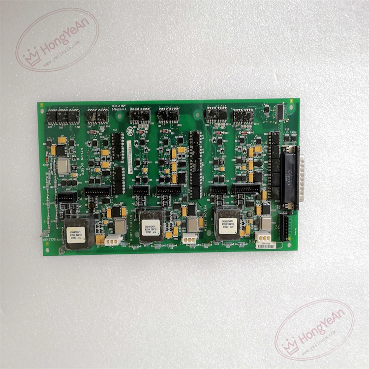
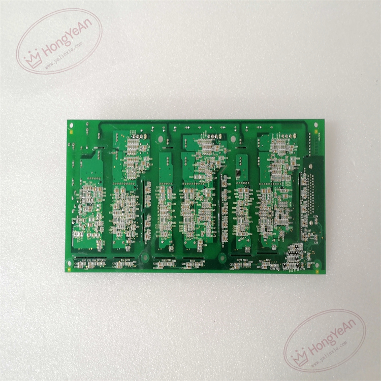
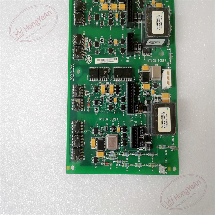
Description
Hardware & Electrical Specifications
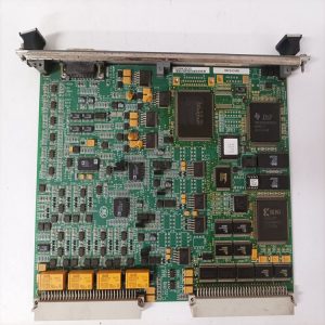
- Model:IS210AEBIH3BEC
- Part Number:IS210AEBIH3BEC
- Module Type:AE Bridge Interface I/O Pack
- Mounting:Installed in Mark VIe I/O pack rack, connected to control network via IONet field‑bus
- Power supply:24 VDC field auxiliary power supplied from rack backplane; typical power consumption <15 W
- Analog bridge input:Multi‑channel differential bridge input for strain‑gauge and differential excitation feedback signals; built‑in precision programmable bridge excitation source
- Discrete input:Multi‑channel galvanic‑isolated wet/dry discrete contact input for permissive, limit‑switch and equipment‑status feedback
- Channel isolation:Enhanced galvanic channel‑to‑channel isolation for high‑EMI industrial environment
- Communication:Dual‑port IONet high‑speed serial communication interface for redundant data exchange with main control processor
- PCB treatment:BEC‑revision enhanced conformal coated for dust‑moisture‑corrosion resistance, improved ESD and surge immunity
- On‑board protection:ESD protection, MOV surge suppression, bridge‑sensor open‑/short‑circuit detection, discrete‑input fault diagnosis, local watchdog self‑monitor circuit, communication link fault detection
- Compatibility note:Cannot run standalone; must match Mark VIe system controller and corresponding field terminal assemblies; full signal‑loop simulation test mandatory after replacement.
Environmental Specifications
- Operating temperature:‑20 ℃ ~ +65 ℃
- Storage temperature:‑40 ℃ ~ +85 ℃
- Relative humidity:5%‑95% non‑condensing
- Installation location:Indoor turbine control cabinet
- EMC compliance:IEC 61000‑6‑2
- Certifications:CE
Mechanical Data
- Weight:approx 0.38 kg
- Dimension:Standard Mark VIe I/O pack form‑factor
- Handling note:ESD‑sensitive PCB; high‑precision weak‑signal bridge‑measurement circuit, anti‑static wrist‑strap mandatory during handling
- Terminal tightening torque:0.6‑1.0 N·m
Main Functions
- Provide stable programmable excitation source for field bridge‑type sensors, receive differential analog signals from strain‑gauges, excitation feedback transducers and position‑related bridge instruments.
- Complete signal conditioning, noise filtering and high‑precision A‑D conversion, convert bridge differential signals into engineering‑unit digital values.
- Acquire multi‑channel discrete contact status signals for auxiliary‑equipment interlock, permissive and fault‑feedback logic.
- Transmit processed analog and discrete data to main Mark VIe / EX2100 controller via redundant IONet bus.
- On‑board channel‑level self‑diagnosis: detect bridge‑sensor open‑circuit/short‑circuit, signal over‑range, discrete‑input abnormality, watchdog timeout and dual‑IONet communication link failure; upload fault alarm to turbine main controller.
- LED status indication:
- Green LED:Module power supply normal / RUN status
- Yellow LED:IONet bus communication active
- Red LED:I/O‑channel fault / module FAIL alarm
Installation & Wiring Requirements
- Cut off rack power supply before replacement. Hot‑swap is forbidden for non‑hot‑swap configuration; strictly follow Mark VIe maintenance procedure for hot‑swap version. Strict anti‑static protection when handling PCB board.
- Insert I/O pack into designated rack slot, secure locking mechanism; ensure backplane bus connection is reliable.
- Field sensor wiring strictly follow GE Speedtronic Mark VIe wiring manual; bridge‑signal cables adopt high‑quality shielded twisted‑pair, strictly separated from high‑power cables; connect shielding to dedicated ground terminal.
- Complete protective grounding according to GE system specification.
- After replacement: verify module power‑on status, check each‑channel analog and discrete reading, simulate sensor fault condition before commissioning.
- Replacement note: For TMR triple‑redundant system application, hardware consistency of related redundant packs shall be verified; full signal‑loop simulation test mandatory before unit put‑into‑service.
-300x300.jpg)
Reviews
There are no reviews yet.