Description
Technical Data
- Model: T9100@F2, belongs to ICS Triplex 9100 safety instrumented system series
- Safety certification: SIL2 approved, meets IEC61508 standards for safety loops
- Architecture: Triple modular redundancy, 2oo3 voting mechanism, single slice fault will not shut down the whole system
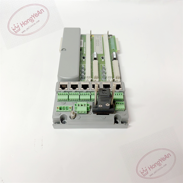
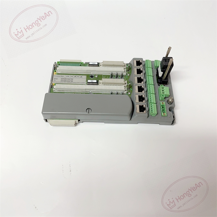
- Interface: Multiple Ethernet ports for redundant communication links, standard backplane slots for CPU and I/O module insertion
- Power supply: 24VDC rack power input
- Mounting: 19 inch standard rack installation inside control cabinet
- Environmental range: Operating temperature -40℃ ~ +70℃; storage -40℃ ~ +85℃; relative humidity 5%–95% non-condensing
- Protection rating: IP20, only for indoor cabinet installation, not for direct field exposure
- Hot swap support: Supported for individual I/O modules on the backplane under correct operation procedure
- Installation guidance: The backplane must be fixed securely to cabinet rails. Keep high voltage power cables separated from signal wiring. All card insertion and removal require anti-static protection. Download the project configuration only after full hardware assembly and wiring inspection.
Physical Features
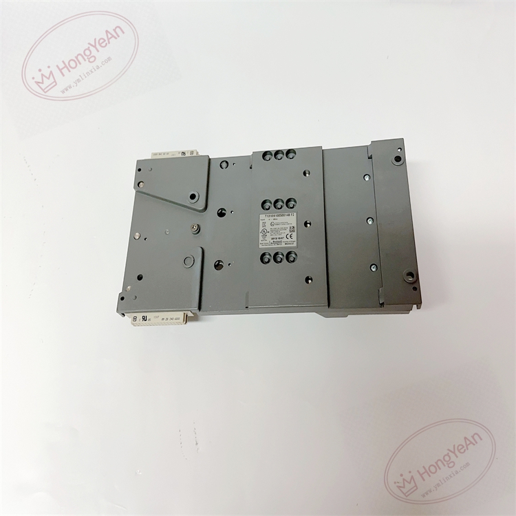
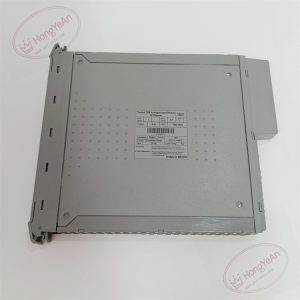
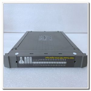
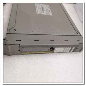
Grey metal frame structure with multiple parallel backplane expansion slots. Terminal blocks and RJ45 Ethernet ports are arranged on the front section. Printed labels on the housing mark the part number and serial code. Gold-plated backplane connectors for stable signal contact. No built-in processor chip; it acts as the carrier and signal bus for all rack modules.
Application Overview
This backplane assembly is widely adopted in petrochemical facilities, oil refineries, gas compressor stations, thermal power plants and offshore platforms. It serves ESD emergency shutdown, burner management and turbine protection safety instrumented loops. It provides mechanical mounting and internal bus communication for redundant processor cards and matching I/O modules, enabling the safety system to collect field process signals and execute interlock trip commands once process parameters exceed safety limits.
Maintenance Notes
This is a safety-critical rack bus component. Loose card insertion or damaged backplane traces will trigger system hardware diagnostic alarms.
- Anti-static wristband must be used during any module plug/unplug work. Isolate related power before maintenance operation.
- Regular inspection needs to check module locking status, LED indicator status, cabinet ventilation and dust accumulation on the backplane.
- After replacing the backplane, verify all module recognition in engineering software, download the full project configuration and carry out complete loop simulation test.
- Keep spare backplane assembly on site. Do not perform soldering or trace repair on site once the backplane circuit is permanently damaged.
Troubleshooting Reference
- Whole rack communication failure: Check 24VDC rack power supply, verify backplane mounting and module locking condition.
- Individual card cannot be recognized: Inspect bent gold fingers, dirty backplane connectors or damaged slot traces.
- Intermittent system heartbeat loss: Check cabinet vibration, loose screws and poor ventilation leading to overheating.
- Diagnostic alarm after backplane replacement: Confirm compatibility with 9100 series CPU and I/O cards, verify bus configuration.
- Overheating warning: Clean dust on backplane, check cabinet fan operation and ambient temperature.
Reviews
There are no reviews yet.