Description
Detailed Technical Data
- Model: T8110C
- Redundancy architecture: Triple Modular Redundancy, adopts 2oo3 hardware voting mechanism. Single slice failure will not interrupt safety logic operation
- Safety certification: IEC61508 SIL3, TÜV, CE, UL approvals, compliant with IEC61511 for process safety
- Processor core: High-performance 32-bit RISC chip, minimum scan cycle 5ms
- Memory allocation: 16MB non-volatile Flash for logic and firmware; 32MB RAM for real-time process data; supercapacitor for temporary data retention during brief power loss
- Power input: Rack backplane 24VDC, acceptable operating range 20~32VDC, typical power consumption 15W
- Communication ports: Dual redundant 10/100Mbps Ethernet TriBus for internal rack I/O bus; dual RS485 serial ports; dedicated front panel diagnostic port for engineering download; supports IRIG-B time synchronization for SOE sequence of event recording
- Hot swap: Supported, online replacement available under lockout-tagout procedures without full system shutdown
- Compatible hardware: ICS Triplex Trusted T8000 series rack and matching T8000 I/O & FTA assemblies. Not interchangeable with T9300, classic Tricon v9/v11 or CX racks
- Temperature range: Operating -40℃ ~ +70℃; storage temperature -40℃ ~ +85℃
- Humidity: 5%–95% RH, non-condensing
- Enclosure rating: IP20, only suitable for installation inside indoor control cabinets
- Built-in diagnostic coverage: Continuously monitors backplane communication, redundant power health, TMR slice mismatch, memory integrity, port link state and hardware fault. All fault information will be uploaded to engineering workstation in real time.
- Installation specifications: Installed in standard 19-inch rack slots. Separate safety network wiring and signal cables from high-current AC power lines. Shielded twisted-pair cables shall be used for all external communication links and implement single-point grounding according to project design. Anti-static protection is mandatory during card insertion and removal. Download full project configuration after hardware installation and wiring inspection.
Physical Attributes
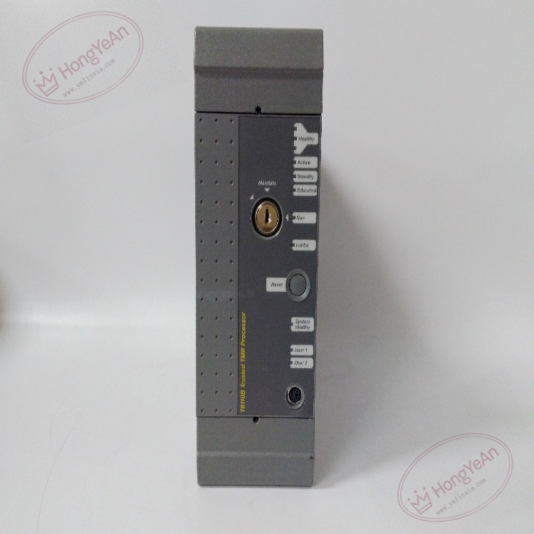
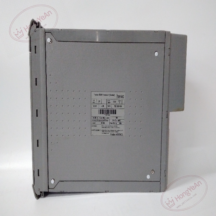
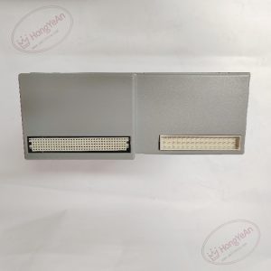
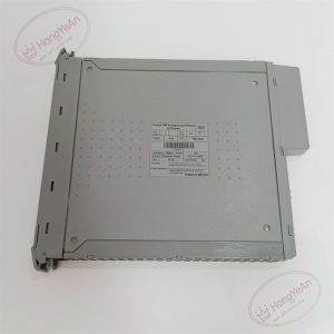
Robust metal front panel integrated with key lock switch and multi-color LED indicators, including power, run status, redundancy fault and communication heartbeat lights. Gold-plated backplane edge connectors ensure reliable contact with rack bus. Three independent internal processing slices to realize triple modular redundancy. Passive metal heat sink for thermal dissipation. Product label printed on side housing with model, serial number and firmware version information. No field-serviceable discrete components on PCB.
Industrial Application
This processor serves as the core logic calculation unit for safety instrumented systems used in petrochemical complexes, oil refineries, gas compressor packages, thermal power plants and offshore platforms. It is widely deployed within ESD emergency shutdown, burner management and turbomachinery protection safety loops. It collects real-time process values from analog and digital I/O modules, executes safety interlock algorithms, and outputs trip commands to field solenoid valves once process variables cross predefined safety thresholds. It also transmits alarm signals, system diagnostic status and time-stamped SOE event logs to DCS and operator HMI for plant monitoring and post-incident analysis.
Maintenance Guidance
Continuous background self-diagnostics detect hardware failure, communication interruption and redundancy loss automatically. All module plug and unplug operations require anti-static wristbands. Isolate related rack power before maintenance work. During routine site inspection, check LED indication, cabinet ventilation, dust accumulation on heat sink and backplane connection status. Clean cabinet dust periodically to prevent leakage current and overheating. After processor replacement, download complete project configuration and firmware matching the hardware version, then perform full loop simulation test to verify all interlock logic works correctly. Maintain spare processor modules on site. Replace the whole unit when permanent hardware failure occurs. Component-level repair on site is forbidden.
Troubleshooting Checklist
- Module cannot boot, all LEDs off: Verify rack 24VDC power supply, inspect module seating in backplane slot, check rack common fuse status
- Redundancy mismatch alarm: Compare firmware version of three TMR slices, inspect backplane internal bus, run dedicated TMR hardware self-test
- Intermittent communication heartbeat loss: Check Ethernet cable integrity, fiber/copper connector cleanliness, switch port status and IP parameter matching
- Logic abnormal after module swap: Confirm full project configuration download, verify firmware compatibility, recheck hardware I/O address mapping
- Overheating warning: Inspect cabinet fan operation, remove dust accumulated on heat sink, reduce cabinet ambient temperature
Reviews
There are no reviews yet.