Description
Key Technical Parameters
- Supported signals: 4~20mA standard analog current signals
- Number of channels: 8 isolated input channels
- Resolution: 16-bit high precision sampling
- Redundancy structure: Triple Modular Redundancy, 2-out-of-3 voting mechanism. Single slice failure will not affect normal signal acquisition.
- Power supply: Supplied by rack backplane 24VDC
- Hot swap: Supports online replacement under standardized operation procedures
- Safety certification: IEC 61508 SIL3, FM, CE, UL certified
- Applicable rack: ICS Triplex T8000 series SIS platform. Not compatible with T9300 or classic Tricon v9/v11 systems.
- Operating temperature: -40℃ ~ +70℃; storage temperature: -40℃ ~ +85℃
- Humidity requirement: 5%–95% relative humidity, non-condensing
- Protection level: IP20, only for installation inside industrial control cabinets
- Built-in diagnosis: Real-time monitoring of loop break, short circuit and signal over-range, diagnostic information can be viewed in engineering software
- Installation tips: Match with designated FTA termination panels and special ribbon cables. Separate instrument signal cables from high-power cables. Shielded wiring must adopt single-point grounding according to project specifications.
Physical Characteristics
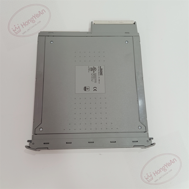
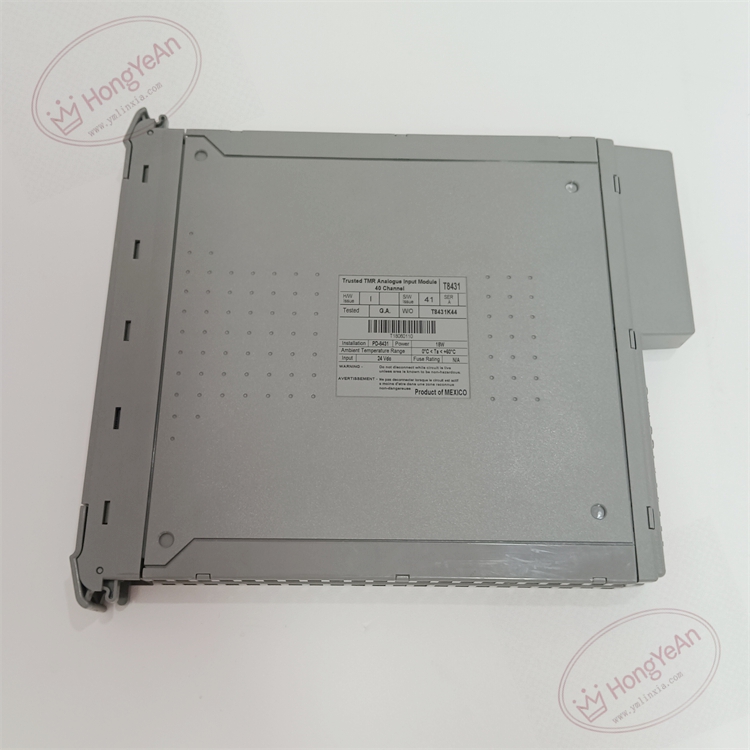
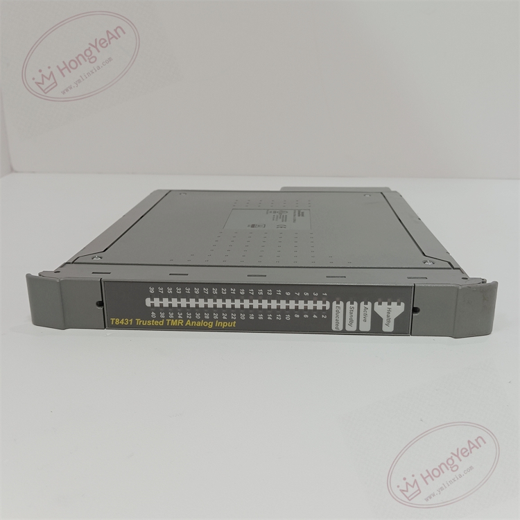
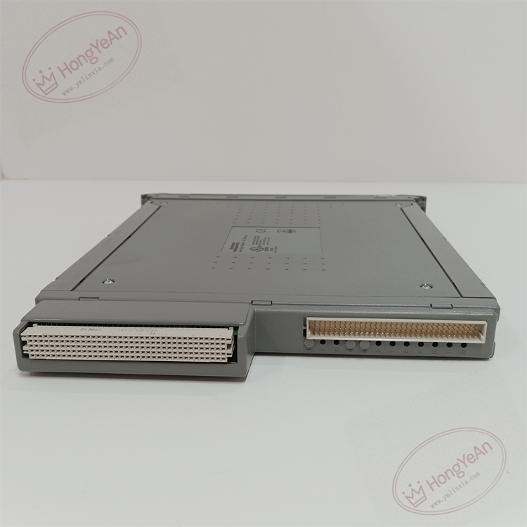
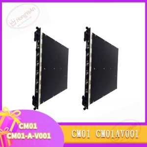
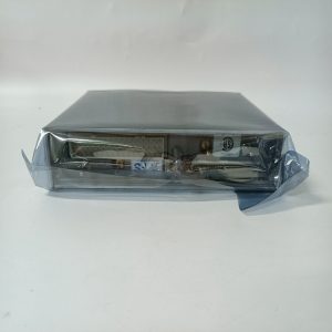
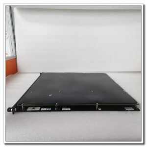
Metal front panel integrated with LED indicators for power, channel state and module fault. Gold-plated backplane connector for rack insertion. Inside the module are three independent sampling circuits to realize TMR redundancy. The product label printed on the card surface marks the model and serial number.
On-site Application
This analog input module is widely applied in petrochemical plants, oil refineries, gas compressor stations, thermal power plants and offshore platforms. It serves safety loops such as ESD emergency shutdown, burner management and turbine protection. It receives pressure, temperature and level signals from field transmitters. Once the measured process value exceeds the safety threshold, the safety system will execute corresponding interlock and shutdown actions.
Maintenance Requirements
The module runs continuous self-diagnosis for each channel. Faults such as wire breakage or short circuit will trigger system alarms. All operations of plugging and unplugging modules need anti-static wristbands, and cut off the power of related field loops in advance. Daily inspection should focus on checking the LED status and system diagnostic information, and confirm whether the card is firmly seated in the rack slot. After module replacement, download the correct hardware configuration, conduct point-by-point signal simulation test, and verify the reading accuracy of each channel. Spare modules should be reserved on site. Replace the whole module directly when hardware is permanently damaged. On-site disassembly and component repair are not allowed.
Common Troubleshooting
- Zero or full-scale reading: Check transmitter power supply, terminal tightness, cable continuity and wiring polarity
- Unstable and fluctuating measurement: Check shield grounding, electromagnetic interference, loose terminals caused by cabinet vibration
- Channel over-range alarm: Confirm transmitter calibration and range setting; check for open or short circuit of field cables
- System reports channel error after replacement: Confirm that T8431 matches the rack and FTA, verify pin assignment and configuration download
-300x300.jpg)
Reviews
There are no reviews yet.