Description
Core Technical Specifications
- Channel layout: 16-channel TMR analog input, primary input range 4–20mA, also compatible with 0–20mA signal.
- Fault tolerance: Three independent sampling circuits run synchronously with hardware 2oo3 voting. Continuous self-check is executed for every channel.
- Circuit diagnosis: Each channel supports loop monitoring to detect wire open, short circuit and transmitter failure. Channel range and alarm thresholds can be set independently.
- SOE function: Hardware high-precision timestamp capture for signal changes and loop faults.
- Power supply: Powered by rack backplane 20–32VDC, with reverse polarity and overvoltage protection. Hot-swap is available when the rack has spare slots.
- Environmental rating: Operating temperature -40℃ ~ +70℃, storage temperature -40℃ ~ +85℃, relative humidity 5%–95% non-condensing. Conformal coated PCB to withstand dust and mild corrosive gas inside control cabinets.
- Spare replacement note: Check firmware version after installing spare parts and match project configuration. Mismatched firmware or improper parameter setup may lead to signal drift, false loop fault alarms or frozen measured values.
Hardware Profile
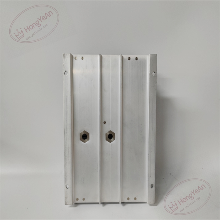
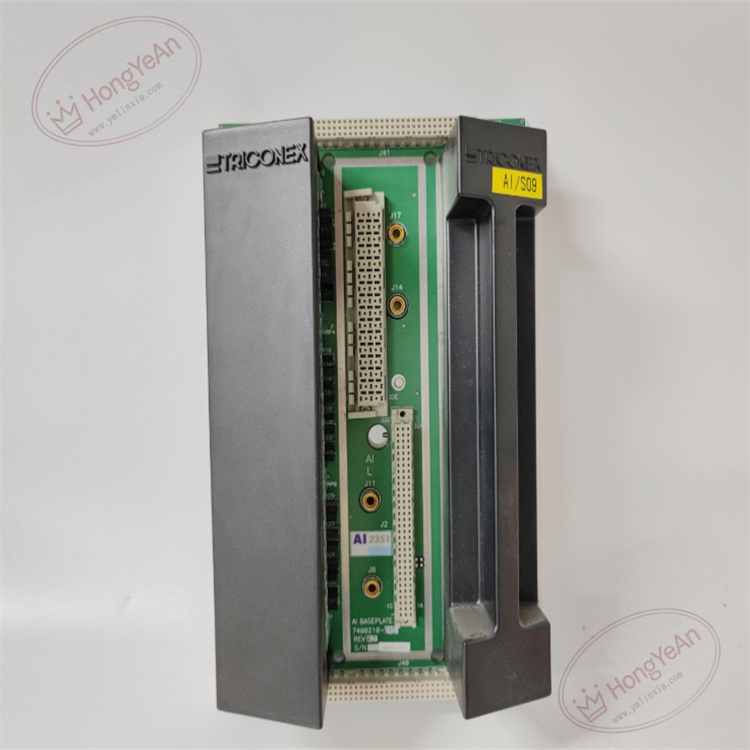
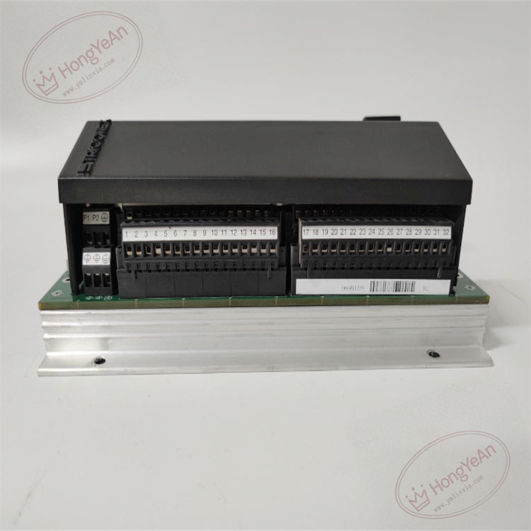
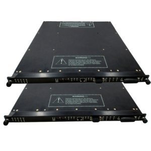
Rack plug-in module. Multiple LED indicators on the front panel display module run status, bus synchronization and channel fault information. High-density gold fingers on the rear side connect to rack backplane for power supply and internal safety bus communication. No field wiring terminals on the module itself. All field instrument cables are connected via matched terminal base. Model label is printed on the side of module housing.
Practical Application Scenarios
It is widely installed in ESD and F&G safety cabinets of petrochemical, refinery, natural gas and power plants. It collects pressure, level, temperature and gas concentration signals from field transmitters and sends validated measurement data to the main processor for emergency shutdown judgment.
Maintenance reminder: This is safety-related component. Complete module failure will cause loss of all 16 process measurement points and disable relevant safety protection loops. Module diagnostic status needs regular inspection during daily maintenance.
Installation & Maintenance Guidance
- Apply anti-static protection during handling. Hot-swap operation is allowed with spare slot; otherwise power off the rack before module insertion or removal.
- Use shielded twisted pair cables for analog signal loops. Keep cables away from inverters and high-power motors to reduce electromagnetic interference. Tighten all terminal connections to avoid unstable readings caused by poor contact.
- Fully insert module into the slot to guarantee reliable contact of backplane gold fingers. Download validated project configuration and set channel range and loop monitoring parameters. Complete channel-by-channel signal simulation test on site, confirm measurement value update and SOE log work normally. Check system event log for version mismatch and bus communication alarms.
- Keep full backup of project configuration files. Do not disassemble damaged module on site; replace the whole unit directly once hardware failure occurs.
Rapid Fault Diagnosis
- Multiple channels report loop fault at the same time: Check wiring on terminal base, search for short or open circuit of field cables and verify transmitter power supply.
- Measured value fluctuates irregularly: Check configuration parameters, cable shielding grounding and terminal tightness, also inspect the health of field transmitters.
- Missing or abnormal timestamp in SOE log: Verify system global clock synchronization and module definition in hardware configuration.
- System alerts firmware version mismatch: Compare firmware revision between spare module and project, inspect gold fingers for dust and oxidation.
- No LED light on front panel: Check backplane power voltage and confirm full insertion of module.
-300x300.jpg)
Reviews
There are no reviews yet.