Description
Main Technical Parameters
- Channel configuration: 16-channel TMR digital input, rated for 24VDC field contact signals.
- Fault tolerance: Three independent signal sampling circuits working synchronously, continuous built-in self-test for each channel.
- Circuit diagnostics: Supports loop monitoring to identify open circuit, short circuit and abnormal contact status.
- SOE function: Hardware timestamp recording for signal status changes and loop faults.
- Power source: Powered by rack backplane 20–32VDC, with reverse polarity and overvoltage protection. Hot swap supported if spare slots are configured.
- Ambient requirements: Operating temperature -40℃ ~ +70℃, storage temperature -40℃ ~ +85℃, humidity 5%–95% non-condensing. Conformal coating on PCB to resist dust and mild corrosive gas in control cabinets.
- Spare installation note: Check firmware revision after spare module installation and align with project configuration. Wrong firmware or improper parameter setup may cause signal loss or false fault alarms.
Hardware Description
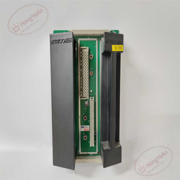
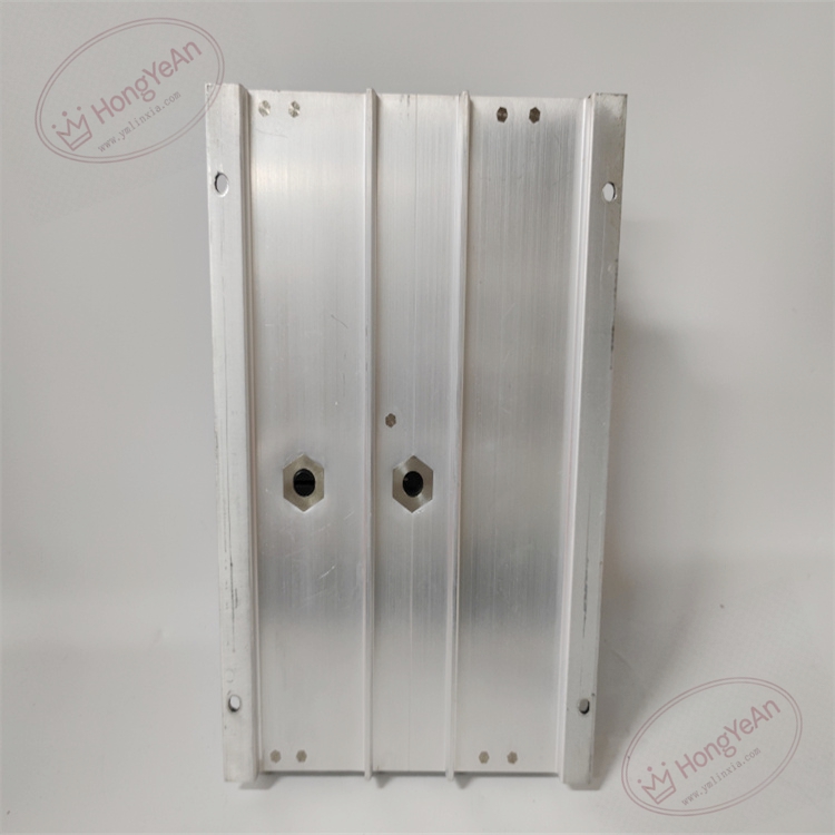
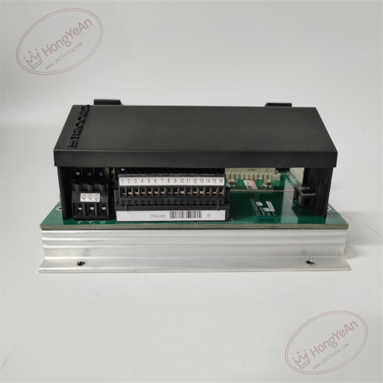
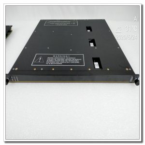
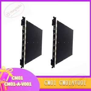
Rack mount plug-in unit. Front panel fitted with LED indicators showing running state, bus sync status and channel faults. Rear gold fingers connect to rack backplane to get power and communicate over the internal safety bus. No wiring terminals on the module itself; all field cables connect to the matched terminal base. Model marking is located on the side of module housing.
Typical Field Applications
Commonly deployed in ESD and F&G safety cabinets of petrochemical plants, refineries, natural gas facilities and power stations. It collects status signals from emergency stop buttons, valve position switches, fire and gas detectors, then sends validated data to the main controller for safety interlock judgment.
Maintenance Note: This safety-critical hardware. Complete module failure leads to loss of all 16 discrete input signals, disabling related safety monitoring loops. Regular checks on module diagnostic status are required during routine inspection.
Installation and Maintenance Instructions
- Wear anti-static equipment during handling. Hot swap is available for spare slot configuration. Power off the whole rack for module replacement without spare slots.
- Adopt shielded twisted pair cables for signal wiring. Separate signal cables from inverters and high-power motors to reduce electromagnetic interference. Fasten terminal screws tightly to prevent unstable contact.
- Push the module fully into the slot to ensure good contact of backplane gold fingers. Load validated project configuration and set relevant loop parameters. Carry out point-by-point signal tests on site, verify signal collection and SOE recording function. Review system logs for version mismatch and bus communication warnings.
- Maintain complete backups of project configuration files. Do not disassemble faulty modules on site; replace the whole module directly once hardware damage occurs.
Quick Troubleshooting Guide
- Multiple channels report loop faults simultaneously: Inspect wiring on terminal base, check field cables for open/short circuit and confirm 24V field power supply.
- Signal reading is unstable: Check terminal tightness, cable grounding and field contact condition.
- SOE logs missing or timestamps disordered: Confirm system clock synchronization and hardware configuration of this module.
- System reports firmware mismatch: Compare firmware version of spare module, clean dust and oxidation on backplane gold fingers.
- All front panel LEDs off: Check backplane supply voltage and confirm full insertion of the module.
Reviews
There are no reviews yet.