
Description
Core Specifications
- Processor chip: Dual 50MHz 32-bit MPC860 processors, one for logic calculation and the other for I/O & communication management.
- Memory allocation: 6MB Flash memory, 16MB DRAM, 32KB battery-backed SRAM for retaining critical data.
- Internal bus: 25Mbps proprietary TriBus for inter-processor synchronization and I/O data transmission.
- Communication ports: 10/100Mbps Ethernet port, supporting Modbus TCP and host communication.
- Power requirement: 24VDC backplane supply, built-in reverse polarity and overvoltage protection. Hot-swap is available under redundant rack configuration.
- Ambient parameters: Operating temperature 0℃ ~ +60℃, storage temperature -40℃ ~ +85℃, relative humidity 5%–95% non-condensing. Conformal coated PCB for better resistance against dust and mild corrosive gas.
- Spare replacement note: Firmware version verification is mandatory after module replacement. Mismatched firmware will lead to synchronization failure, frozen I/O data or communication breakdown.
Module Physical Description
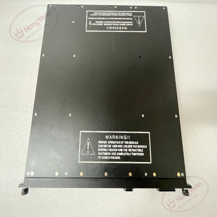
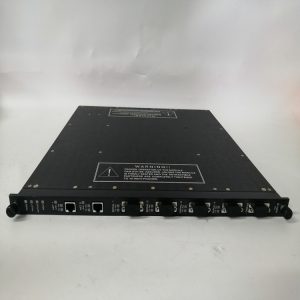
Rack plug-in processor card. Multiple LED indicators are arranged on the front panel, displaying running status, triple-channel synchronization, fault alarms and network link status. Gold fingers on the rear side connect with rack backplane to obtain power and transfer TriBus data. No field wiring terminals are equipped on this processor card. The model marking is printed on the side of the metal housing.
Typical Application Scenarios
It is widely deployed in ESD and F&G safety cabinets of petrochemical, refinery, natural gas and power plants. The module collects signals from I/O cards, executes safety interlock logic, and sends shutdown commands to field actuators. Redundant processor configuration ensures the system can continue operating under single-point fault and reduce unplanned shutdown risks.
Maintenance Reminder: This is safety-critical core hardware. Total failure of the processor will disable all safety protection loops of the subsystem. Regular inspection on module synchronization and diagnostic status is required.
Installation & Maintenance Guide
- Wear anti-static wristband during handling. Hot swap is allowed for redundant processor slots. Power off the whole rack before replacement without redundant setup.
- Use shielded industrial Ethernet cables. Keep network wiring away from inverters and high-power motors to reduce electromagnetic interference. Inspect cable connectors regularly for loose contact.
- Push the module fully into the rack slot to guarantee stable gold finger contact. Match firmware revision, download validated project program and finish system synchronization. Observe front panel LEDs and check system logs for version mismatch and bus alarms.
- Keep complete backup of project source program and firmware files. Do not disassemble damaged processor on site; replace the whole unit directly once permanent hardware damage occurs.
Quick Troubleshooting Tips
- System reports processor leg mismatch: Check firmware consistency, clean dust and oxidation on backplane gold fingers.
- Processor synchronization failure: Inspect TriBus inter-processor cables and eliminate electromagnetic interference.
- All I/O data stops updating: Confirm processor running state and verify complete program download.
- No LED light on front panel: Check rack backplane 24V power supply and confirm full insertion.
- Frequent communication alarms: Inspect Ethernet cables, connectors and switch working status.
-300x300.jpg)
-300x300.jpg)
Reviews
There are no reviews yet.