Description
Technical highlights
Input power range: 20‑35 VDC. Output nominal 18.4 VDC, maximum field‑side current 80 mA. Complies with Fieldbus Foundation Type133 IS power supply specificationEaton. Built‑in software‑selectable bus terminator switch. Green LED indicates module power status. Certified for Zone0 / Zone1 hazardous‑area installation per ATEX / IECEx standards. Operating ambient:‑20℃~+60℃; storage‑40℃~+85℃; humidity 5‑95% non‑condensing; IP20 cabinet‑mount only. Compatibility note: Dedicated for FF‑H1 fieldbus segments. Observe 10 mm spacing between adjacent modules for heat dissipation. Improper termination will trigger bus communication instabilityEaton.
Physical features
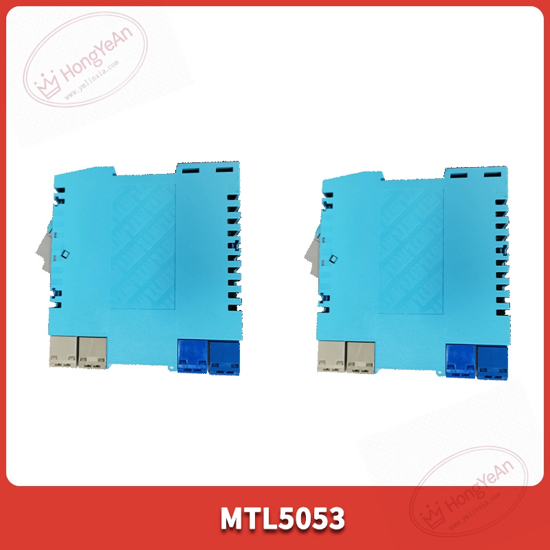
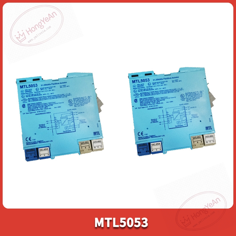
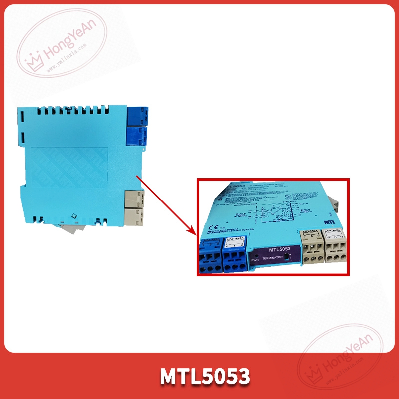
Compact blue DIN‑rail housing form factor. Top side has removable plug‑in screw terminals for safe‑side power and fieldbus wiring; termination selector switch is located on upper edge. Front face mounts power‑status LED indicator. Part‑number MTL5053 is printed on module front label. Internal circuit board uses conformal coating for anti‑dust performance in plant cabinet surroundingsEaton.
Site application scenario
Installed inside control cabinets for oil‑gas, chemical and power‑plant sites. It provides intrinsically‑safe power and electrical isolation for fieldbus transmitters and actuators located in explosive hazardous zones. Module failure will cut off fieldbus segment power, all field devices on this H1 segment go offline. After replacement, mount on standard T35 DIN‑rail, set terminator switch according to actual bus layout, check power LED status, verify fieldbus device online condition before commissioningEaton.
Installation & maintenance notes
Disconnect DC power before module replacement. Anti‑static handling is required. Use shielded fieldbus‑compliant cable. Follow fieldbus segment length rules and termination requirements. Keep signal cables separated from high‑power power cables to reduce electromagnetic interference. Maintain 10 mm clearance between neighbouring modules for heat dissipation. Do not stack modules tightly togetherEaton. On‑site component‑level repair is prohibited. Replace complete unit under permanent hardware damage.
Common site fault performances
- All fieldbus instruments on segment offline: Check 24 VDC input power supply, inspect terminator switch setting and fieldbus cable integrity.
- Bus communication intermittent fluctuation: Verify module mounting spacing and heat dissipation, check cable shielding and grounding quality.
- Power LED remains off: Inspect DC input loop and module internal fuse.
- Partial field devices cannot be detected: Review total segment current load, confirm it does not exceed 80 mA maximum output limit.
Reviews
There are no reviews yet.