
Description
Main Technical Parameters
- Redundancy Design: TMR triple modular redundancy, synchronous operation of three separate processing channels with hardware 2oo3 voting.
- Storage & Memory: Expanded flash memory for safety application program storage, battery-backed SRAM to retain critical runtime and fault event data.
- Communication Interfaces: Dual 10/100Mbps Ethernet ports, proprietary TriBus internal bus, support Modbus TCP and TriStation configuration connection.
- Power Input: 24VDC rack backplane power supply, operating range 18–32VDC. Integrated reverse polarity and overvoltage protection. Hot swap available under redundant processor rack configuration.
- Environmental Specifications: Operating temperature 0℃ ~ +60℃, storage temperature -40℃ ~ +85℃, relative humidity 5%–95% non-condensing. Conformal coated PCB to resist dust and mild corrosive gas in control cabinets.
- Spare Module Installation Tips: Firmware compatibility check is required before downloading project software after replacement. Incompatible firmware will result in synchronization failure, frozen I/O values or interrupted network communication.
Hardware Features
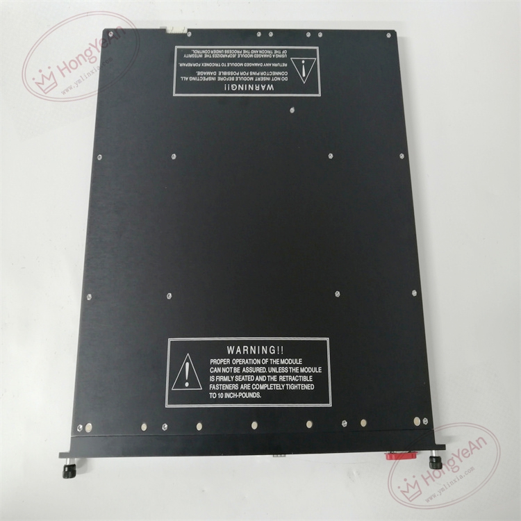
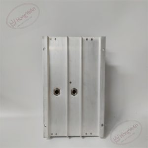
Rack plug-in processor card. A set of LED indicators on the front panel displays module run status, triple leg synchronization, fault alarms and network link health. Gold fingers on the rear side connect with rack backplane for power supply and TriBus data transmission. There are no field wiring terminals on this processor card. Model information is printed on the side of the metal housing.
Field Application Scenarios
This processor is widely installed in ESD and F&G safety cabinets for petrochemical plants, refineries, natural gas stations and thermal power plants. It collects signal data from all I/O modules, executes safety interlock logic, and transmits emergency shutdown commands to field actuators. Deploying redundant processors allows continuous system operation when a single point fault occurs and lowers the risk of unplanned plant shutdown.
Maintenance Note: This is safety-critical core hardware. Complete processor failure will disable all safety protection loops within the subsystem. Technicians must regularly check module synchronization status and diagnostic alarms during routine maintenance.
Installation & Maintenance Guidelines
- Wear anti-static wristbands for all module handling. Hot swap operation is permitted for racks with redundant processor slots. If no redundant configuration exists, power off the whole rack before module removal or insertion.
- Use shielded industrial Ethernet cables. Route network wiring away from inverters and high-power motors to reduce electromagnetic interference. Inspect cable connectors periodically for loose connections.
- Push the module fully into the rack slot to ensure reliable contact of backplane gold fingers. Confirm firmware revision, download validated project program and finish system synchronization. Observe front panel LEDs and review system logs for version mismatch and bus communication warnings.
- Keep complete backups of project source code and firmware files. Never disassemble faulty modules on site; replace the whole unit directly once permanent hardware damage occurs.
Quick Troubleshooting Reference
- System reports leg mismatch alarms: Verify firmware consistency of three channels, clean dust and oxidation on backplane gold fingers.
- Processor synchronization failure: Inspect TriBus inter-processor cables and eliminate electromagnetic interference sources.
- All I/O data stops updating: Check processor operating state and confirm full completion of program download.
- No LED illumination on front panel: Check rack backplane 24V power supply and confirm full module insertion.
- Repeated network communication alarms: Inspect Ethernet cables, connectors and switch operating condition.

Reviews
There are no reviews yet.