Description
Core Technical Specifications
- Channel allocation: 64 commoned digital input points, software selectable for 24VDC or 48VDC. Input working range 20–72VDC.
- Redundancy design: Three independent scanning legs with dedicated microprocessor on each leg. Continuous per-channel self-check.
- Diagnostic functions: Loop fault detection and stuck state test to identify abnormal contact and circuit failures.
- Internal communication: Data transmission and leg synchronization via proprietary TriBus.
- Power supply: Powered by rack backplane 20–32VDC. Built-in reverse polarity and overvoltage protection. Hot-swap is supported for racks with spare slots.
- Ambient rating: Operating temperature -40℃ ~ +70℃, storage temperature -40℃ ~ +85℃, relative humidity 5%–95% non-condensing.
- Spare replacement note: Verify firmware revision after module replacement. Mismatched firmware may trigger signal deviation, false fault alarms or frozen input readings.
Physical Characteristics
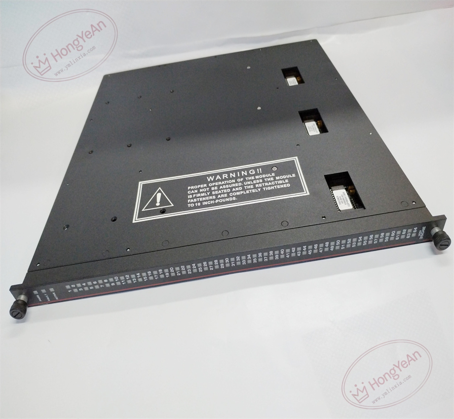
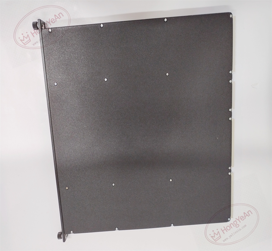
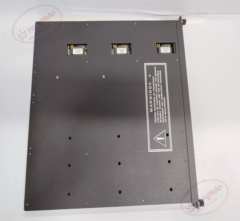
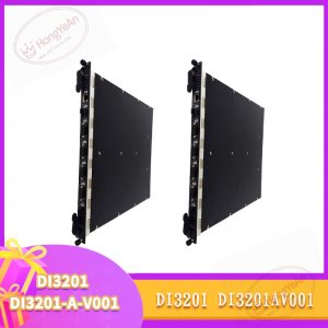
Rack plug-in I/O card. Front panel is equipped with LED indicators to show module running state, triple leg synchronization and module fault status. Gold fingers at the rear connect with rack backplane for power supply and TriBus communication. No field wiring terminals on the module itself. All field instrument cables are routed to the matched external termination panel. Model code is printed on the side of module housing. Mechanical keying prevents wrong slot installation.
Typical Industrial Usage
This high-density input card is widely applied in ESD and F&G safety cabinets of petrochemical plants, natural gas compressor stations and power generation facilities. It collects status feedback from emergency stop buttons, valve limit switches and gas detectors. High channel density reduces the total number of required rack slots and saves cabinet space.
Maintenance Reminder: This is safety-related hardware. Full module failure leads to loss of all 64 input points and disables relevant safety monitoring loops. Regular inspection of diagnostic alarms is required.
Field Operation & Maintenance Guide
- Wear anti-static wristband during handling. Hot swap is available with spare slot configuration. Power off the whole rack for replacement without redundant setup.
- Deploy shielded twisted pair cables for field signal wiring. Separate signal cables from high-power motor and inverter cables to reduce electromagnetic interference. Tighten terminal screws to avoid intermittent contact issues.
- Fully insert module into rack slot to guarantee stable gold finger contact. Download validated project configuration and run point-by-point signal simulation test. Confirm signal collection works normally and check system logs for version mismatch and bus alarms.
- Keep complete backup copies of project configuration files. Never disassemble damaged module on site; replace the whole unit directly once permanent hardware damage occurs.
On-site Troubleshooting Checklist
- Batch channels report loop faults: Inspect wiring on termination panel, check field cables for open/short circuit and verify 24/48VDC field power supply.
- Individual signal reads intermittently: Check terminal tightness, cable shielding grounding and field contact health.
- System triggers leg mismatch alerts: Confirm firmware consistency, clean dust and oxidation on backplane gold fingers.
- No LED lights on front panel: Check rack backplane power and confirm full module insertion.
- All input values stop updating: Verify TriBus link status and main processor running condition.
-300x300.jpg)
Reviews
There are no reviews yet.