Description
Core Technical Parameters
- Channel configuration: 8 non-commoned pulse input channels, 16-bit high resolution. Measuring frequency range from 1kHz to 20kHz.
- Redundancy design: Triple parallel sampling circuits, continuous built-in self-test for each individual channel.
- Signal adaption: Supports signals from magnetic speed sensors and pulse output transducers.
- Diagnosis: Real-time monitoring to detect open circuit, short circuit and signal loss of field sensor loops.
- Internal bus: Transmit validated frequency and pulse data to main processors via TriBus.
- Power supply: 20–32VDC backplane power input, integrated reverse polarity and overvoltage protection. Hot-swap function available for racks with spare slots.
- Environmental rating: Operating temperature -40℃ ~ +70℃, storage temperature -40℃ ~ +85℃, relative humidity 5%–95% non-condensing. Conformal coated PCB option for dusty, humid and mildly corrosive cabinet environments.
- Spare replacement note: Verify firmware compatibility after installing spare module. Inconsistent firmware will trigger reading deviation, false loop fault alarms or frozen frequency values.
Physical Characteristics
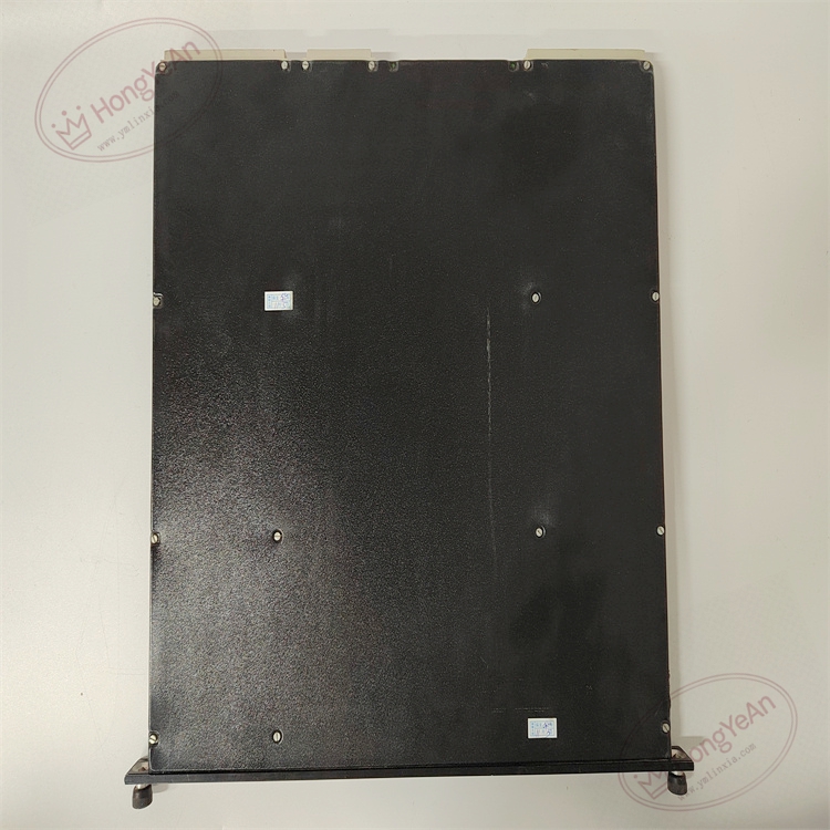
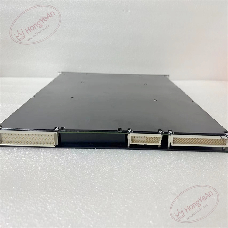
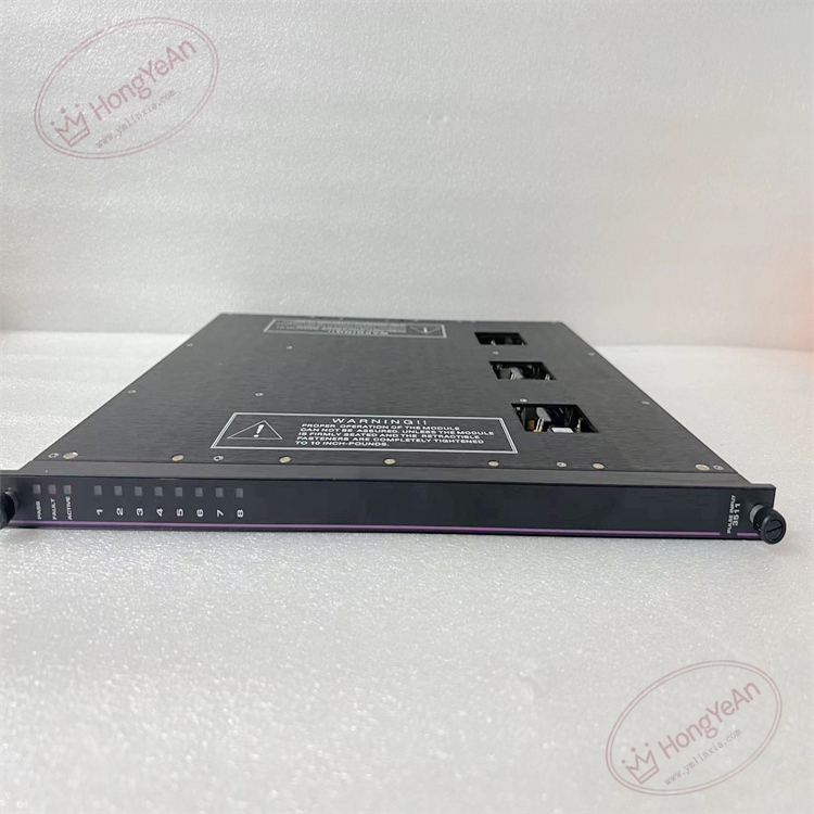
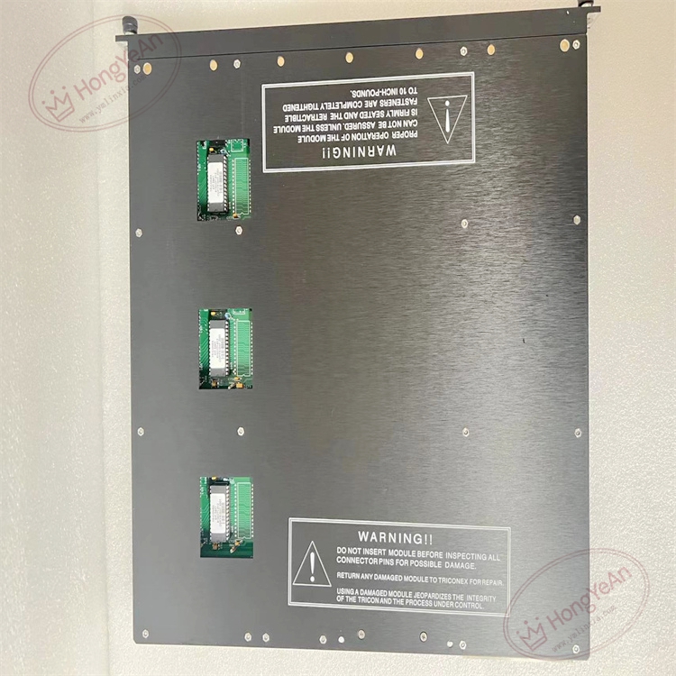
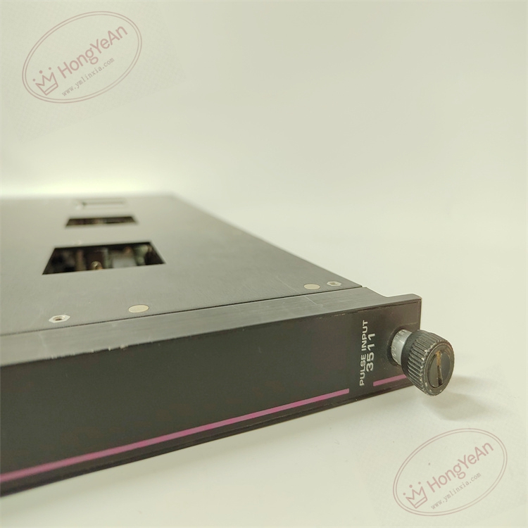
Rack plug-in I/O card. The front panel is equipped with LED indicators for module running status, triple leg synchronization and fault alerts. Gold fingers on the rear side connect with rack backplane to obtain power and exchange TriBus data. No field wiring terminals on the module itself. All sensor cables are wired to matched terminal bases. Model marking is printed on the side of the module housing.
Typical Industrial Applications
This pulse input module is widely deployed in ESD safety cabinets of petrochemical plants, natural gas compressor stations and thermal power plants. It receives pulse signals from turbine and compressor speed probes, calculates rotation speed and sends validated measurement data to Tricon processors for overspeed protection judgment.
Maintenance Reminder: This safety-related hardware. Complete module failure leads to loss of all 8 pulse measuring points and disables overspeed protection for rotating machinery. Technicians must check module diagnostic status regularly during routine inspection.
Handling & Service Instructions
- Wear anti-static wristband for all module handling. Hot swap operation is allowed for racks with redundant spare slots. Power off the whole rack before replacement without redundant configuration.
- Use shielded twisted pair cables for pulse signal wiring. Separate sensor cables from high-power cables of motors and inverters to reduce electromagnetic interference. Tighten terminal screws properly to avoid unstable pulse readings.
- Insert the module fully into rack slot to guarantee reliable gold finger contact. Download validated project configuration and carry out point-by-point signal simulation test. Confirm frequency measurement updates normally and check system logs for version mismatch and bus communication warnings.
- Keep complete backup copies of project configuration files. Never disassemble damaged module on site; replace the whole unit directly once permanent hardware damage occurs.
On-site Troubleshooting Checklist
- Multiple channels report sensor loop faults: Inspect wiring on terminal base, check field cables for open or short circuit and verify sensor power supply.
- Frequency reading fluctuates heavily: Check terminal tightness, cable shielding grounding and installation gap of speed probes.
- System triggers leg mismatch warnings: Confirm firmware consistency, clean dust and oxidation on backplane gold fingers.
- No LED lights on front panel: Check rack backplane power supply and confirm full module insertion.
- All pulse values stop updating: Verify TriBus link and running status of main processor.
-300x300.jpg)
Reviews
There are no reviews yet.