Description
Key Technical Data
- Channel configuration: 32 commoned digital output channels, rated 24VDC for field loads.
- Redundancy mechanism: Three separate output circuits, continuous built-in self-test for each individual channel.
- Circuit diagnosis: Advanced loop supervision to detect blown fuses, wire open/short circuit and load anomalies. Supports switchable supervised / unsupervised operation modes.
- Internal bus: Reliable data exchange and leg synchronization through proprietary TriBus.
- Power supply: 20–32VDC backplane power input, integrated reverse polarity and overvoltage protection. Hot-swap is available for racks with redundant spare slots.
- Environmental specs: Operating temperature -40℃ ~ +70℃; storage temperature -40℃ ~ +85℃; relative humidity 5%–95% non-condensing. Conformal coated PCB option is available for cabinets with dust, moisture and mild corrosive vapor.
- Spare replacement reminder: Verify firmware compatibility after module replacement. Mismatched firmware may trigger false load fault alarms or failed output execution.
Physical Characteristics
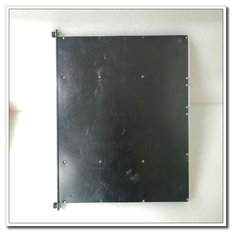
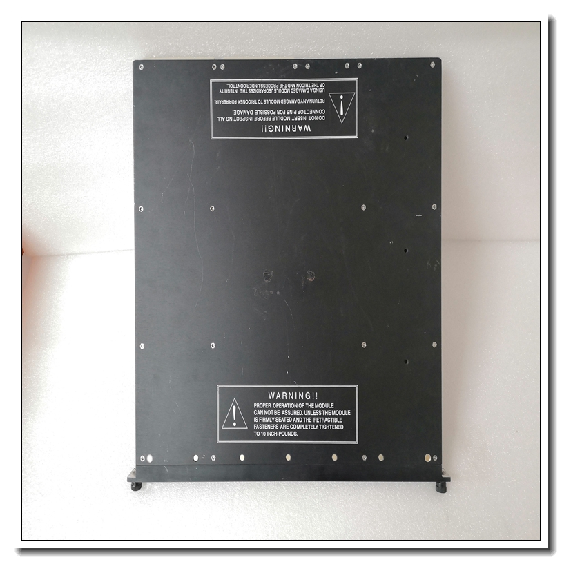
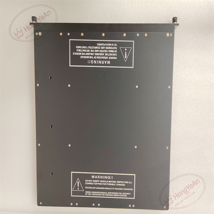
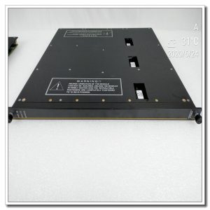
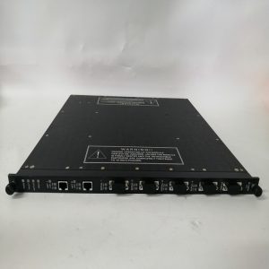
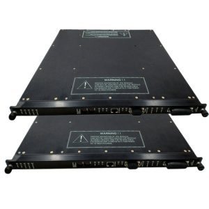
Rack plug-in output card. The front panel integrates LED indicators to display module running state, triple leg synchronization and channel fault alerts. Gold fingers at the rear interface with rack backplane to get power and transmit TriBus data. No field wiring terminals on the module itself. All solenoid valve cables are wired to supporting terminal base. Model marking is printed on the side of the metal housing.
Site Deployment Cases
This upgraded output module is widely installed in ESD emergency shutdown and F&G fire & gas safety cabinets for offshore platforms, coastal chemical plants, natural gas compressor stations and thermal power facilities. It executes shutdown commands sent by main processors to control emergency cut-off valves, blowdown valves and sound-light alarm equipment. Enhanced diagnostic capability helps technicians discover hidden circuit faults ahead of time.
Maintenance Reminder: This hardware belongs to safety-critical components. Complete module failure will cause loss of all 32 output points and disable relevant safety protection loops. Regular inspection of diagnostic alarms is required during routine maintenance.
Handling & Service Guidance
- Wear anti-static wristband during module handling. Hot-swap can be performed on racks with redundant spare slots. Power off the whole rack before module removal or insertion without redundant setup.
- Adopt shielded twisted pair cables for field output wiring. Separate control cables from high-power cables of motors and inverters to reduce electromagnetic interference. Tighten terminal screws properly to avoid intermittent poor contact.
- Insert the module fully into rack slot to guarantee stable gold finger contact. Download validated project configuration and run point-by-point function test. Confirm field actuators respond correctly and check system logs for version mismatch and bus communication warnings.
- Retain complete backup copies of project configuration files. Never disassemble damaged module on site; replace the whole unit directly once permanent hardware damage occurs.
Field Troubleshooting Checklist
- Multiple channels trigger load fault alarms at once: Inspect wiring on terminal base, check field cables for open/short circuit, verify 24V field power supply and fuse health.
- Actuator does not respond after output command: Check safety logic configuration, solenoid coil status and terminal tightness, confirm channel lock caused by overload.
- System reports leg mismatch alerts: Verify firmware consistency across three legs, clean dust and oxidation on backplane gold fingers.
- No LED lights on front panel: Check rack backplane power supply and confirm full insertion of module.
- Output status cannot update: Inspect TriBus connection and running condition of main processor.
Reviews
There are no reviews yet.