Description
Detailed Specifications
- Channel setup: 4 analog output channels. Signal range is software configurable, supporting 4–20mA current or ±10V voltage output, with adjustable zero point and gain parameters per individual channel.
- Output performance: 12-bit D/A resolution. Typical static accuracy reaches ±0.1% full scale. Output response time ≤2ms, capable of fast adjustment for valve position control. Max load resistance for 4-20mA current loop is 750Ω.
- Redundancy & self-test: Three independent output legs run synchronously. Hardware voting mechanism ensures valid output even if one leg fails. Continuous background diagnostics monitor loop status, capable of detecting wire break, short circuit and actuator load abnormality.
- Internal bus: Control setpoints and diagnostic alarms are transmitted to and from Tricon main processors via proprietary TriBus. Three legs maintain time synchronization to keep voting results consistent.
- Power requirement: 20–32VDC backplane power supply, integrated reverse polarity and overvoltage protection. Hot-swap maintenance is supported for racks with redundant spare slots.
- Environmental specs: Operating temperature -40℃ ~ +70℃; storage temperature -40℃ ~ +85℃; relative humidity 5%–95% non-condensing. Conformal coated variant is available for cabinets with dust, moisture and mild corrosive vapor.
- Spare installation note: Firmware version must match the existing Tricon system after replacement. Version mismatch may lead to output offset, sporadic false loop fault alarms or synchronization failure of three legs.
Physical Characteristics
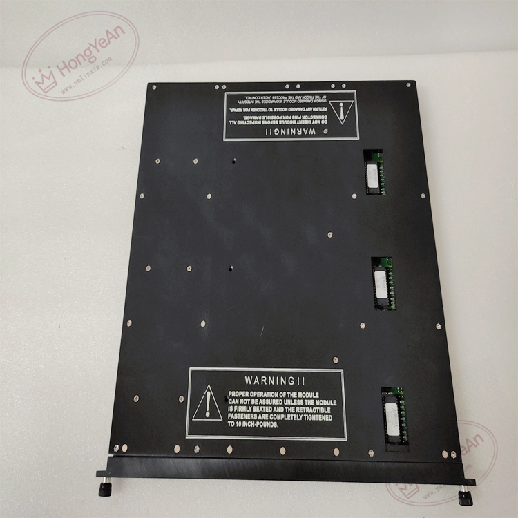
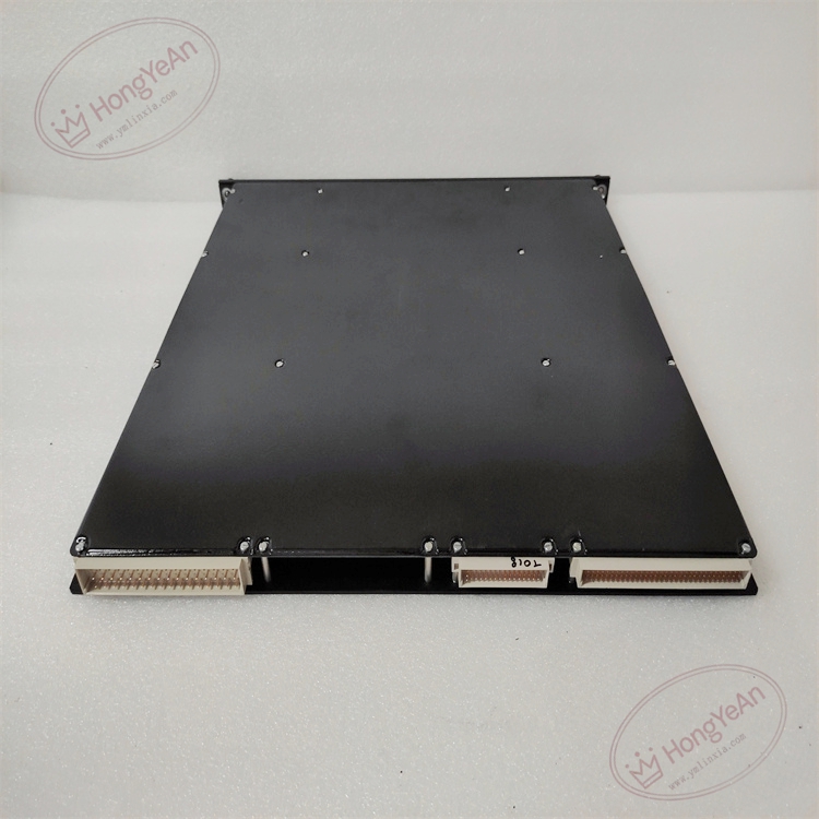
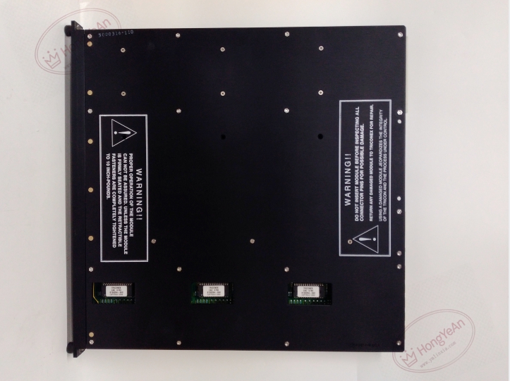
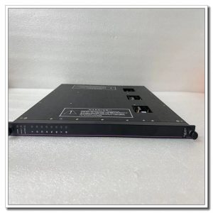
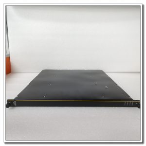
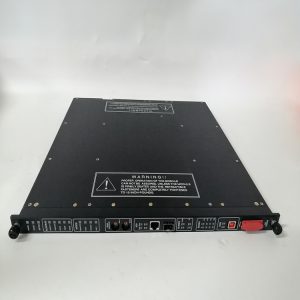
Rack plug-in analog output board. The front panel is equipped with multi-color LED indicators showing module running state, triple leg synchronization and channel fault alerts. Gold finger contacts at the rear connect with rack backplane for power delivery and TriBus data exchange. There are no field wiring terminals on the module itself. All valve cables land on matched external terminal base assemblies. Model marking is printed on the side of metal housing, and mechanical keying prevents mismatched installation.
Site Application Scenarios
This analog output module is widely deployed in petrochemical plants, oil refineries, natural gas compressor stations, thermal power plants and offshore platforms. It is used within ESD emergency shutdown and burner management safety loops, delivering analog control signals to position modulating valves. The high precision and fast response make it suitable for safety-related valve position regulation.
Maintenance Reminder: Safety-critical I/O hardware. Complete module failure will cut off control signals for all 4 output channels, and relevant safety loops will switch actuators to predefined safe state. Technicians need to regularly review diagnostic alarms and inspect cable integrity during routine site maintenance.
Operation & Maintenance Suggestions
- Anti-static wristband must be worn during module handling. Hot-swap maintenance can be carried out on racks with redundant spare slots. If there is no redundant configuration, shut down the whole rack power before removing or inserting the module.
- Shielded twisted pair cables are required for field analog output wiring. Separate control cables physically from high-power motor and inverter cables to reduce electromagnetic interference. Tighten terminal screws with suitable torque; loose terminals often cause output drift and unstable valve action.
- Insert the module fully into rack slot to guarantee stable gold finger contact. Download validated project configuration after installation and run point-by-point output calibration test. Confirm valve position changes synchronously with setpoint adjustment, then check system logs for leg version mismatch and internal bus communication warnings.
- Keep complete backup copies of project configuration files and firmware. Never disassemble faulty module on site; replace the whole unit directly once permanent hardware damage occurs.
Field Troubleshooting Reference
- Channel triggers loop fault alarms: Inspect wiring on terminal base, check field cables for open or short circuit and verify power supply for valve positioners.
- Analog output drifts or fluctuates: Check terminal tightness, cable shield grounding and working health of field valve positioners.
- System raises leg mismatch warnings: Confirm firmware consistency of three legs, clean dust and oxidation on backplane gold finger contacts.
- No LED lights on front panel: Verify rack backplane power supply and confirm module is fully seated in slot.
- Output value cannot change: Check TriBus link status and running condition of Tricon main processor.
-300x300.jpg)
Reviews
There are no reviews yet.