Description
Detailed Specifications
- Channel setup: 16 software-configurable universal channels. Single channel can be set to analog input, digital input, analog output or digital output independently. Supported signal types: 4–20mA / 0–10V analog signals, 24VDC discrete signals. Built-in HART pass-through function for smart field transmitters.
- Measurement & control performance: Analog accuracy ±0.5% full scale. Fast channel scanning cycle ensures timely response for safety trips. Each channel supports independent parameter setup for range, alarm threshold and fail-safe action.
- Redundancy & self-test: Three independent signal processing legs operate synchronously. 2-out-of-3 hardware voting suppresses wrong readings from single leg failure. Continuous background diagnostics monitor every channel, detecting cable break, short circuit and field device anomaly without interrupting safety operation.
- Internal bus: Process values, output commands and diagnostic events are exchanged with Tricon CX main processors via TriBus. Inter-leg time synchronization guarantees consistent voting results.
- Power requirement: 20–32VDC backplane power supply, with built-in reverse polarity and overvoltage protection. Hot-swap maintenance is available on racks equipped with redundant spare slots.
- Environmental specs: Operating temperature -40℃ ~ +70℃; storage temperature -45℃ ~ +85℃; relative humidity 5%–95% non-condensing. The hardware is designed to resist vibration and electrical noise inside industrial control cabinets.
- Spare installation note: After replacement, firmware revision must match the existing Tricon CX system. Version mismatch will lead to channel configuration failure, sporadic false loop alarms or synchronization failure between three legs. This module only works for Tricon CX series SIS, incompatible with older Tricon classic racks.
Physical Characteristics
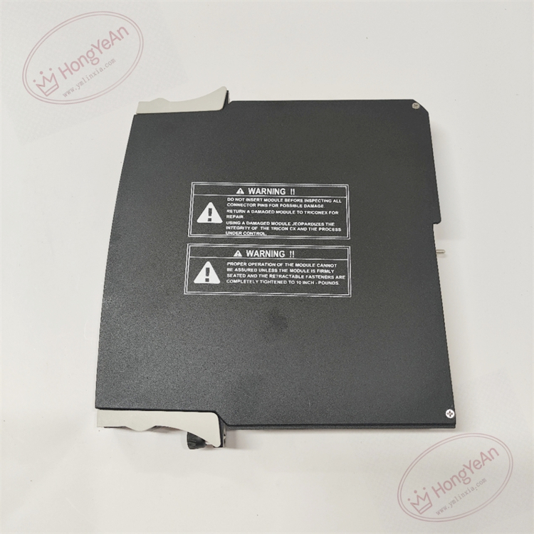
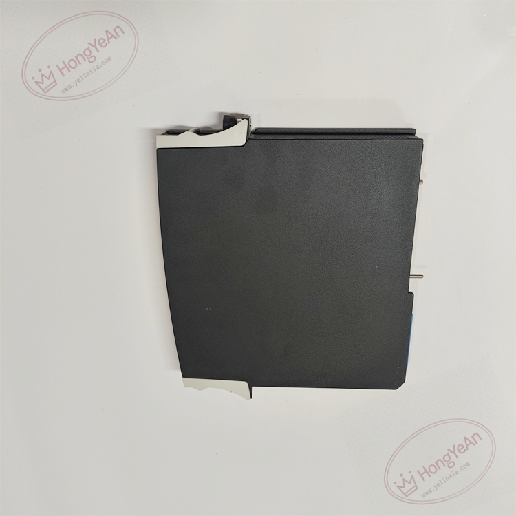
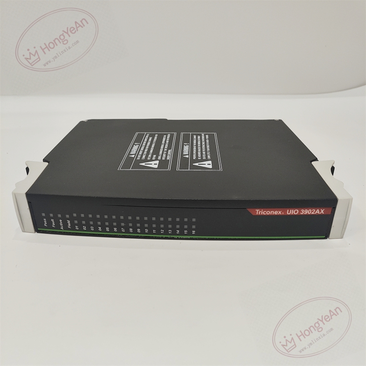
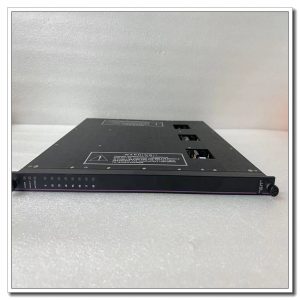
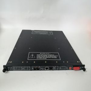
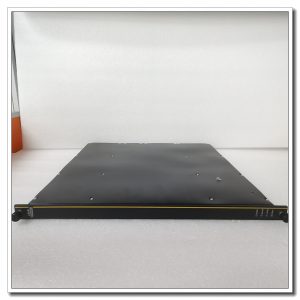
Rack plug-in universal I/O board. Front panel fitted with LED indicators showing module running state, triple leg synchronization and individual channel fault alerts. Gold finger contacts on rear connect with rack backplane for power supply and TriBus data transmission. No field wiring terminals on the module. All field instrument cables connect to matched dedicated terminal base assemblies. Model marking is printed on the side of metal housing, and mechanical keying prevents wrong-slot installation.
Site Application Scenarios
This flexible universal I/O module is widely deployed in ESD emergency shutdown, burner management and turbomachinery protection systems of petrochemical plants, refineries, natural gas compressor stations and thermal power plants. Its multi-function channel design reduces the variety of I/O modules and spare parts inventory, especially for compact safety cabinets with mixed analog and discrete signal points. HART function enables remote diagnostics and parameter reading for smart transmitters, simplifying daily instrument maintenance.
Maintenance Reminder: Safety-critical I/O hardware. Total module failure will cause loss of all 16 universal channels, and related safety loops will trigger predefined safe actions. Technicians need to regularly check diagnostic alarms and cable integrity during routine site inspection.
Operation & Maintenance Suggestions
- Anti-static wristband must be worn for module handling. Hot-swap maintenance is supported for racks with redundant spare slots. If there is no redundant configuration, power off the whole rack before removing or inserting the module.
- Use shielded twisted pair cables for field wiring. Separate instrument cables physically from high-power motor and inverter cables to reduce electromagnetic interference. Keep proper torque for terminal screws; loose terminals will cause signal fluctuation and false diagnostics.
- Insert the module fully into rack slot to guarantee stable gold finger contact. Download validated project configuration after installation, then configure each channel’s I/O type and run point-by-point function test. Confirm input and output respond correctly, and check system logs for leg version mismatch and internal bus warnings.
- Retain complete backup copies of project configuration and firmware files. Never disassemble faulty module on site; replace the whole unit directly once permanent hardware damage occurs.
Field Troubleshooting Reference
- Multiple channels trigger loop fault alarms: Inspect wiring on terminal base, check field cables for open or short circuit and verify power supply for field instruments.
- Signal reading fluctuates intermittently: Check terminal tightness, cable shield grounding and health status of transmitters or actuators.
- System raises leg mismatch warnings: Confirm firmware consistency of three legs, clean dust and oxidation on backplane gold finger contacts.
- No LED illumination on front panel: Verify rack backplane power supply and confirm module is fully seated in slot.
- Channel configuration cannot take effect: Confirm the module firmware and CX system version are compatible, re-download project configuration.
Reviews
There are no reviews yet.