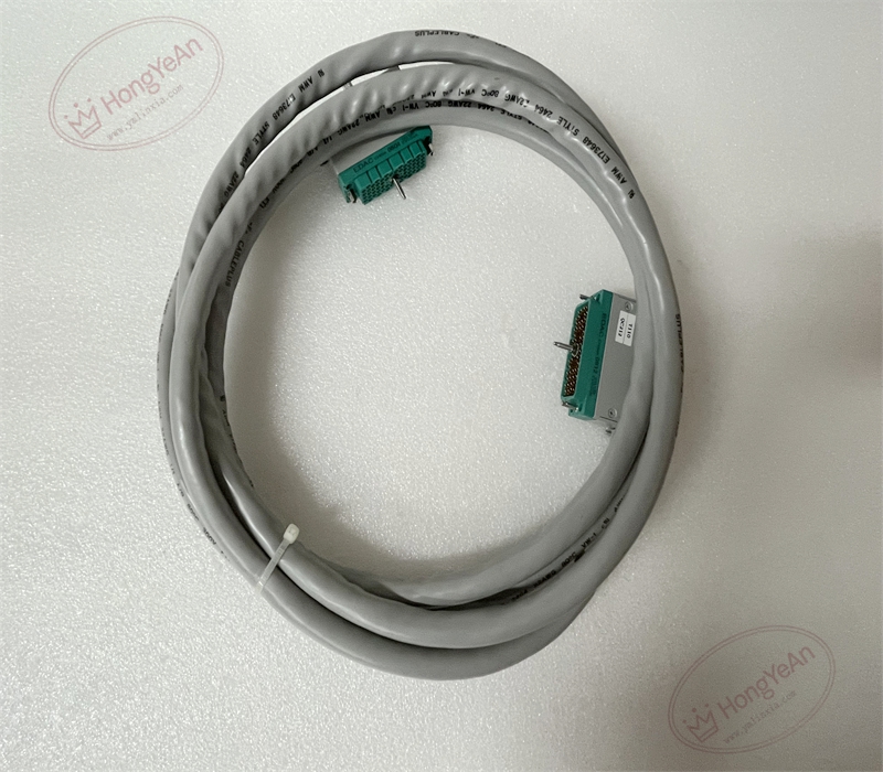
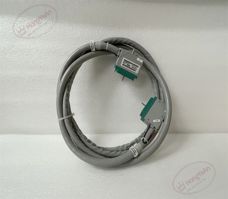
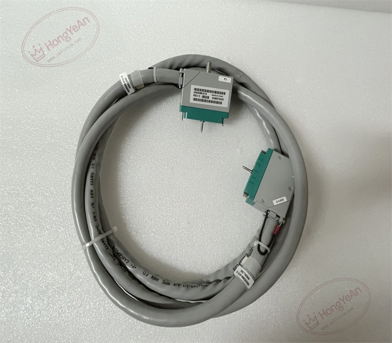
Description
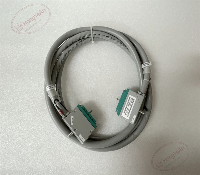
Core Specifications
- Cable construction: Multi-conductor shielded cable, flame retardant insulation, copper braid shielding for anti-interference
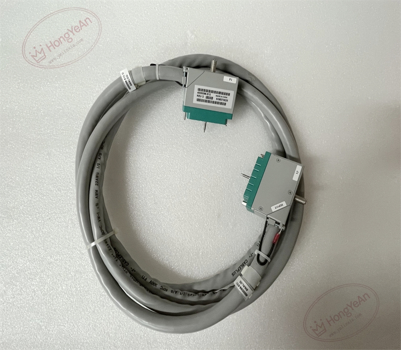
- Connectors: Custom factory molded locking connectors at both ends
- Length: 10ft (3 meters)
- Rated voltage: 300V AC/DC, suitable for 24VDC instrument signal loops
- Platform compatibility: Classic Tricon v9~v11 systems, match DI/DO/AI/AO modules and corresponding marshaling panels. Not applicable to Tricon CX platform.
- Environmental range: Operating temperature -40℃ ~ +85℃; storage temperature -40℃ ~ +85℃; relative humidity 5%–95% non-condensing.
- Installation reminder: Route separately from high-power power cables to reduce electromagnetic interference. Follow single-point shield grounding rules according to SIS project specifications. Avoid sharp bending, pulling or crushing the cable during cabinet wiring.
Physical Construction
Grey flame retardant outer jacket, internal multi-core conductors with overall shielding and drain wire. Both ends are equipped with molded dedicated multi-pin connectors with locking buckles. Part number marking is printed on the cable label and connector housing.
Application Areas
This cable assembly is widely used in petrochemical plants, refineries, gas compressor stations, thermal power plants and offshore platforms. It is applied in ESD emergency shutdown, burner management, turbomachinery protection and fire & gas safety instrument systems. It connects Tricon rack I/O cards and termination panels to ensure stable transmission of safety measurement and trip signals.
Maintenance Note: This is safety-related signal transmission hardware. Damaged cable or loose connector lock will trigger channel diagnostic alarms. Routine maintenance needs to check connector locking condition, cable sheath integrity and routing protection.
Operation & Maintenance Suggestions
- Wear anti-static wristband before plugging or unplugging connectors. Cut off the power of the related field loop before disconnecting the cable.
- Keep cabinet interior clean. Prevent sharp metal edges from scratching the cable jacket, and keep corrosive vapor and liquid away from the cable and connectors.
- After wiring, lock the connector clips tightly. Conduct point-by-point signal simulation test, verify signal transmission stability, and check system diagnostic logs for cable-related faults.
- Prepare spare cables of the same model. Do not splice or repair damaged cables on site. Replace the whole assembly once the cable insulation or connector pins are permanently damaged.
Common Fault Handling
- All connected channels have no signal: Check the connector locking status, inspect cable breakage or pin damage of molded plug.
- Intermittent signal fluctuation: Check shield grounding quality, cable compression, cabinet vibration and loose connectors.
- Single channel signal failure: Inspect internal wire breakage or bent pins on the connector.
- Diagnostic alarms after cable replacement: Confirm cable matches I/O module and termination panel, verify pin assignment.
- Cable sheath scratch: Check friction with cabinet metal edges and add protective sleeves.
Reviews
There are no reviews yet.