Description
Key Specifications
- Cable construction: Multi-conductor flame retardant cable with tinned copper braid shielding and drain wire to reduce electromagnetic interference
- Connectors: Custom molded multi-pin plugs with mechanical locking clips
- Length: 10ft (3 meters)
- Voltage rating: 300V AC/DC, suitable for 24VDC instrument signal loops
- System compatibility: Classic Tricon v9 to v11 TMR platform. Matches DI, DO, AI, AO modules and corresponding termination panels. Not compatible with Tricon CX.
- Ambient parameters: Operating temperature -40℃ ~ +70℃; storage temperature -40℃ ~ +85℃; relative humidity 5%–95% non-condensing. Vibration and dust resistant for cabinet installation.
- Installation reminder: Run cable separately from high-power power cables. Adopt single-point shield grounding following project requirements. Avoid sharp bending, pulling or squeezing the cable. On-site splicing is not permitted.
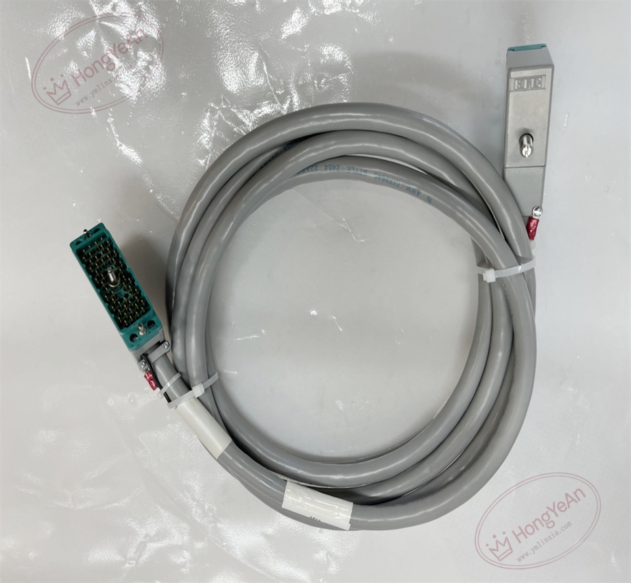
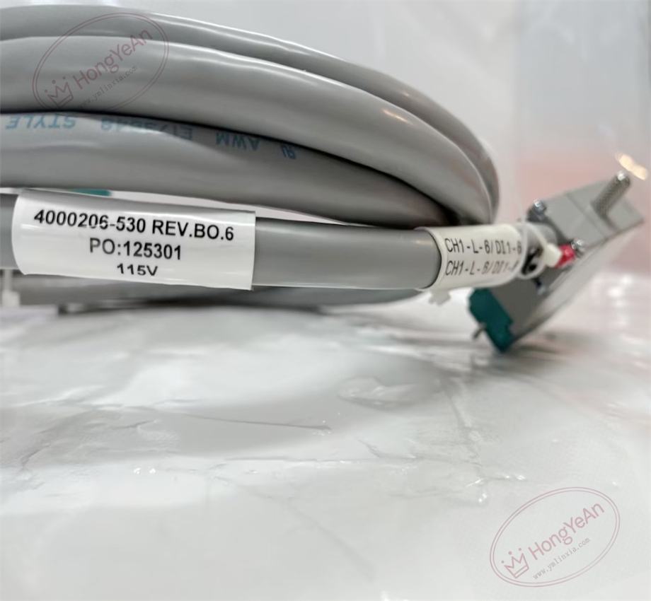
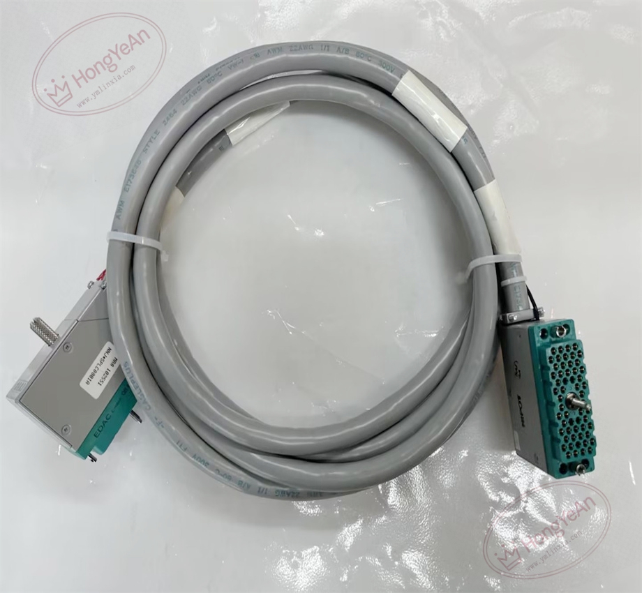
Physical Features Grey flame retardant outer sheath. Internal multi-core signal conductors protected by full copper shielding. Both ends are equipped with integrated custom multi-pin connectors with locking buckles. The part number is printed clearly on cable tags and connector housings. It is a passive wiring component with no electronic chips.
Application Scope It is widely applied in petrochemical plants, refineries, gas compressor stations, thermal power plants and offshore platforms. It serves safety instrumented loops including ESD emergency shutdown, burner management, turbomachinery protection and fire & gas detection systems. It connects Tricon rack I/O cards and termination panels to maintain stable transmission of safety trip and measurement signals.
Maintenance Guidance This is safety-critical signal transmission hardware. Cable damage or unlocked connectors will trigger channel diagnostic alarms.
- Wear anti-static wristband when handling connectors. Cut off field loop power before disconnecting the cable.
- Keep cabinet interior clean. Prevent sharp metal edges from scratching the cable jacket.
- After wiring, fully lock connector clips. Carry out point-by-point signal simulation test and check system diagnostic logs.
- Prepare spare cable assemblies of identical model. Replace the whole assembly once permanent damage occurs; do not repair cables on site.
Troubleshooting Tips
- No signals for all connected channels: Check connector lock status, cable breakage and bent pins of molded plugs.
- Intermittent signal fluctuation: Inspect shield grounding quality, cable compression, cabinet vibration and loose terminals.
- Single channel signal failure: Check broken inner wires or deflected connector pins.
- Diagnostic alarms after replacement: Confirm the cable matches I/O module and termination panel, verify pin assignment.
- Scratched cable sheath: Install protective sleeves to reduce friction with cabinet metal edges.
Reviews
There are no reviews yet.