Description
Detailed Specifications
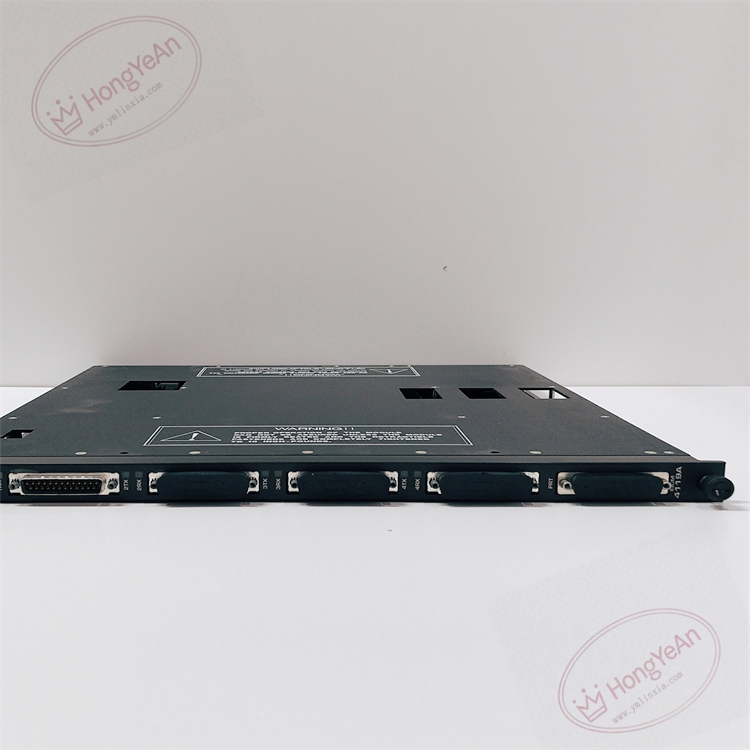
- Port configuration: 4 configurable serial ports, each can be set to RS-232 / RS-422 / RS-485; plus 1 isolated Centronics parallel printer port. 500VDC galvanic isolation between each port and system backplane to block ground loop interference.
- Communication protocol: Supports Modbus RTU / ASCII, TriStation 1131 programming protocol, and printer output. Full set of standard Modbus function codes including coil, discrete input, register read/write and diagnostic loopback test.
- Baud rate options: 1200, 2400, 9600, 19200 baud. Total aggregated throughput of four serial ports maxes out at 57.6 kbps. For RS485 bus, the maximum cable length reaches 1200 meters and can connect up to 32 slave devices.
- System capacity limits: One Tricon rack can install at most two 4119A modules, and these two modules occupy one logical slot together. Each chassis allows up to seven Modbus master instances hosted on this module.
- Internal data link: Exchanges process variables, alarm events and diagnostic messages with Tricon CPU via TriBus. It works as a communication gateway and does not affect local safety interlock logic even if the module fails.
- Power requirement: 20–32VDC backplane power supply, integrated reverse polarity and overvoltage protection. Supports online hot-swap replacement, no need to shut down the whole safety rack during module change.
- Environmental specs: Operating temperature -40℃ ~ +70℃; storage temperature -40℃ ~ +85℃; relative humidity 5%–95% non-condensing. PCB conformal coating is available as an option for dusty, humid cabinets.
- Spare installation note: After replacement, firmware version must match the existing Tricon system. Version mismatch will lead to port configuration failure, garbled serial data or intermittent communication dropouts. This module fits classic Tricon racks, not compatible with Tricon CX platform.
Physical Characteristics
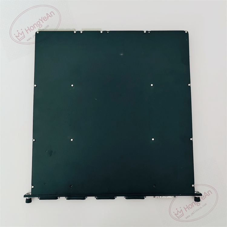
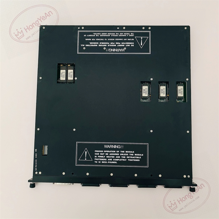
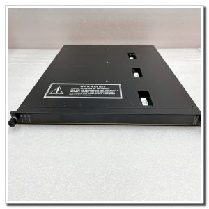
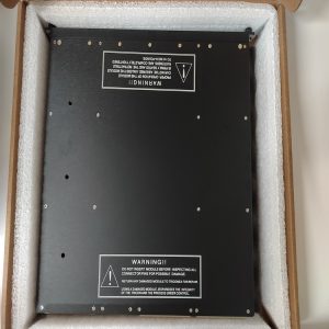
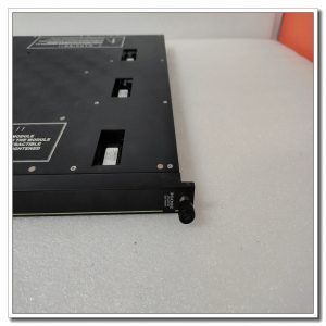
Rack plug-in communication board. Front panel has dedicated LED indicators: module PASS/FAULT status, port active status, TX transmit and RX receive lights for every serial channel. Gold finger contacts on rear connect with rack backplane for power and TriBus data exchange. All serial and parallel external signal connectors sit on the front panel, no field wiring terminals on rear side. Model marking is printed on metal housing, mechanical keying prevents wrong-slot installation.
Site Application Scenarios
This serial communication gateway is widely used in petrochemical plants, refineries, gas compressor stations, thermal power plants and offshore platform SIS systems. It connects Tricon SIS to third-party Modbus devices, DCS systems, local printers and TriStation engineering workstations. RS485 multi-drop bus can collect data from multiple remote Modbus slaves. Since communication module failure does not stop safety trip logic, it is commonly adopted for non-safety-class data transmission between safety rack and external automation systems.
Maintenance Reminder: This is safety-related communication hardware. Module failure will cut off serial data transmission, but the core SIS safety interlock function remains operational. Technicians should regularly check port status, cable integrity and communication error counters during routine maintenance.
Operation & Maintenance Suggestions
- Anti-static wristband must be worn when handling the module. Hot-swap replacement is supported; no rack power-off required. If performing wiring modification, disconnect field serial cable first to avoid static damage to port chips.
- Use shielded twisted pair cables for RS485 / RS422 / RS232 wiring. Separate serial communication cables from high-power motor and inverter cables to reduce electromagnetic interference. Terminate bus resistors at the two extreme ends of RS485 trunk; improper termination causes unstable serial reception.
- Insert the module fully into rack slot to guarantee stable gold finger contact. After installation, configure port parameters including baud rate, parity, protocol and master/slave mode. Carry out point-to-point communication test, verify data read/write is normal and check system logs for leg mismatch and TriBus alarms.
- Keep complete backup copies of project configuration and firmware files. Never disassemble faulty module on site; replace the whole unit directly once permanent hardware damage occurs.
Field Troubleshooting Reference
- Serial port cannot receive or transmit data: Check cable wiring, bus terminal resistor, baud rate and parity consistency between two ends, inspect port TX/RX LED indicators.
- Communication intermittent dropout: Inspect shielding grounding, cable aging and loose terminal connections. RS485 bus overload or excessive slave quantity is a frequent cause.
- System raises leg mismatch alerts: Confirm firmware consistency, clean dust and oxidation on backplane gold finger contacts.
- No LED illumination on front panel: Verify rack backplane power supply and confirm module is fully seated in slot.
- Modbus register reading shows garbled values: Check byte order setting, signal grounding and electrical noise interference on the serial bus.
Reviews
There are no reviews yet.